|
BRHS /
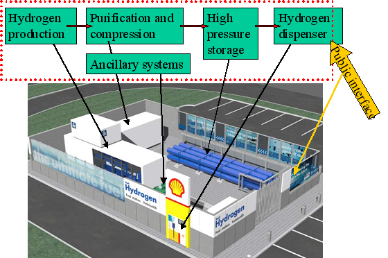
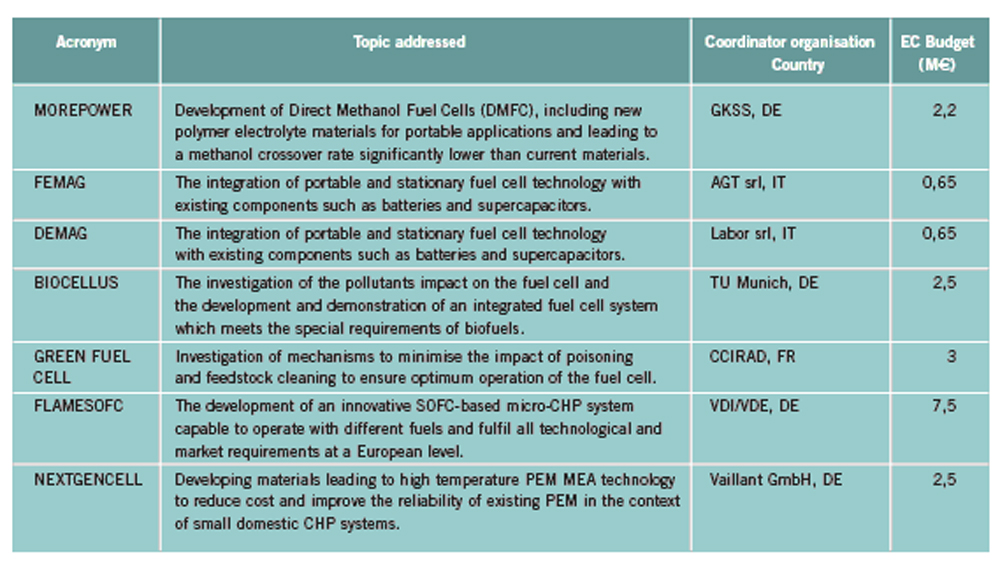
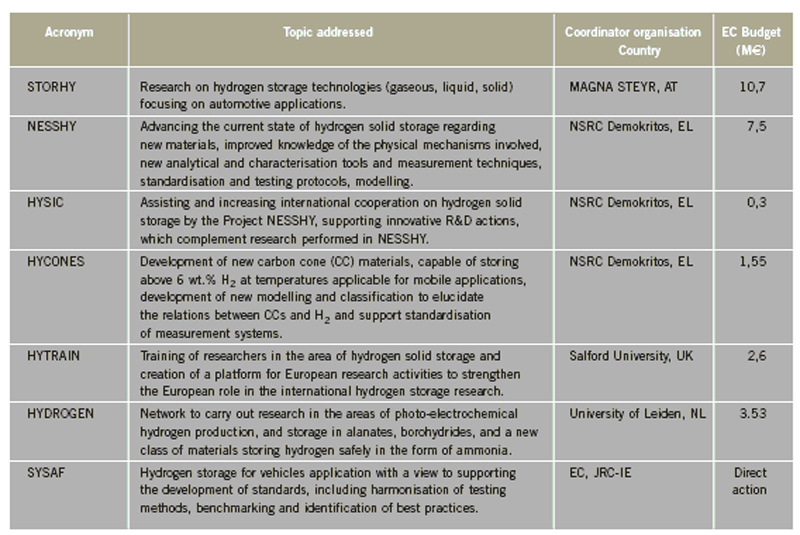
OFD-Chapter 2Chapter 2. Hydrogen TechnologiesHydrogen TodayHydrogen is widely used today as a chemical product in various industries (petrochemical, food, electronics, metallurgical processing etc.). So far, the only significant energy application has been space programs. Hydrogen is however emerging as a major component for a future sustainable energy economy where hydrogen and electricity are foreseen to be complimentary sustainable energy carriers (EuropeanCommission:RTDInfoSpecial:2007) with hydrogen especially valid for movable or portable applications. Hydrogen offers a unique method of reducing the fossil fuel dependency while increasing the usage of renewable energy sources. The main driving forces to introduce hydrogen as an energy carrier are based on the limited fossil fuel resources in general, and the implicit political dependencies creating a widespread and high level political need to secure and diversify national energy supplies (EuropeanCommission:EUR20719EN:2003). Environmental concerns on urban pollution and the greenhouse effect are also important drivers. Hydrogen as an energy carrier is thought to take a key role to combine and to apply different renewable and sustainable energy sources. Concerns over environmental impacts of continued fossil fuel use are leading to development of decarbonisation technologies (IEA:2001). In the short term, it is believed that such technologies will be a source for low-cost hydrogen production. Currently about 90 percent of the world’s hydrogen production is based on fossil fuels and mainly natural gas (NOU:2004:11). In the long term, the production needs to be based on the renewable energy sources in order to reduce the pollution problem in a sustainable way. In the mean time hydrogen production might be based on fossil fuels (natural gas reforming, coal gazification) with CO2 sequestration and H2 production at nuclear installations. Hydrogen as an energy carrier is still in its infancy, and will probably not have a significant market share for 10 to 15 years from now. However, hydrogen production, storage and conversion technologies have reached a technical state which already makes its use as an energy carrier highly interesting -although many improvements and new discoveries are still possible and needed. On the other hand, a number of challenges have to be overcome to make hydrogen a commercially viable large-scale actor on the energy marked. Furthermore, the technology can be expected to change substantially as a consequence of more widespread use of hydrogen. Urban vehicles running on hydrogen are seen as one important application and can contribute to reduced emissions in city centres. This requires that national authorities, industry and research institutes work closely together to facilitate a hydrogen refuelling infrastructure and a regulatory framework allowing safe introduction of commercial hydrogen vehicles and refuelling stations. The development of an improved understanding and knowledge of safety aspects related to hydrogen are very important to facilitate such a process. The same aspects are valid for stationary hydrogen applications, e.g. stationary use of hydrogen fuel cells. In the long term, the vision is the transition to a “hydrogen society” where hydrogen, derived without pollution from renewable energy sources, will become a clean energy carrier as widely used as electricity, with the leading role in all application requiring energy to be stored, for transport in particular. Hydrogen production paths will include solar, water (tidal energy, currents), biological and other renewable energy sources, in theory leading to nearly inexhaustible supplies of hydrogen. Hydrogen can then be utilised in combined heat/power generation, in industry, and in every form of transport in ships, vehicles, trains and aeroplanes. It is expected that fuel cells will be the solution of choice for implementing hydrogen, as this is the cleanest and most efficient means to put this energy vector to use in the application. Coupling renewable energy resources with hydrogen storage will reduce the impact of low/variable capacity factors and enable energy to be supplied when and where needed. Efficient and cost-effective hydrogen storage is therefore a key to the provision of renewable power on demand. In the future, refuelling stations for hydrogen-fuelled vehicles might be part of the infrastructure like conventional gas stations are today. Hydrogen and its associated technologies therefore have to reach safety acceptance by the public and approval by the relevant authorities. There is currently a large, well-established delivery system for hydrocarbon fuels (gasoline, natural gas, propane, etc.). A hydrogen-fuelled fleet of vehicles will require duplication of much of the existing gasoline dominated infrastructure. The very large investments required will be a serious hurdle for the market driven introduction of hydrogen technologies. However, these may be reduced by considering the feasibility and safety of utilizing the existing natural gas pipeline networks for hydrogen transport, as well as on-site production of hydrogen. More information about hydrogen trnsport in natural gas pipelines can be found on the NaturalHy website www.naturalhy.net All these new means of using hydrogen raise the important question of how to ensure the safe introduction of this new energy carrier for use by the general public. References: {European Commission, Directorate-General for Research, Directorate-General for Energy and Transport} (2003) Hydrogen energy and fuel cells, a vision of our future. Final Report of the High Level Group, RTD Info, EUR 20719 EN, Brussels.(BibTeX) Hydrogen Production TechniquesIntroductionIntroductionAlmost all hydrogen on earth is found in compounds, mainly in combination with oxygen as water or in combination with carbon as organic substances. Hydrogen is currently primarily produced from fossil resources, in the first place through reforming of natural gas (48% of the world’s production), but also with processes such as partial oxidation of oil (30%) or the gasification of coal (18%). Biomass gasification, which is still in the demonstration phase, is used on a minor scale to produce a hydrogen and/or methane rich fuel gas. The utilization of the secondary energy carrier “electricity” allows hydrogen production by water splitting via electrolysis, which accounts for approximately 4% of the world’s production. This method, however, strongly depends on the availability of cheap electricity. Largest near-term market for hydrogen will be the petrochemical industries requiring massive amounts of H2 for the conversion of heavy oils, tar sands, and other low-grade hydrocarbons. Hydrocarbon Splitting ProcessesSteam Reforming of Natural Gas Steam reforming of natural gas is a technically and commercially well established technology on industrial scale and currently the most economical route. Reforming technology is mainly used in the petrochemical and fertilizer industries for the production of so-called “on-purpose” hydrogen. Steam methane reforming (SMR) takes place at typically 850°C in the presence of an iron or nickel catalyst. The main processes of heat transfer are radiation and convection. The equilibrium composition of the reformer gas is depends strongly on the fuel characteristics, the steam-to-carbon ratio, outlet temperature and pressure, which are chosen according to the desired products. High reforming temperatures, low pressures and high steam to methane ratio favour a high methane conversion. Optimum pressure range is 2.5-3 MPa resulting in a hydrogen yield of 86-90% (Uhde:2003). A minimum H2O/CH4 ratio of around 2 is necessary to avoid carbon deposition on the catalyst. If excess steam is injected, typically 300% away from the stoichiometric mixture, the equilibrium is shifted towards more CO2 at temperatures of 300-400°C increasing the H2 yield and reducing the undesired production of carbon. The conventional process requires additional stages of desulfurization, CO shift conversion, and purification by pressure swing adsorption (PSA). Overall, the different process steps need considerable amount of energy. The total balance for such a plant is that 1 Nm3 of methane allows the production of 2.5 Nm3 of hydrogen, which corresponds to an overall efficiency of the process of around 65 %. It is rather difficult to get much higher efficiencies in practice. Presently large steam reformer units with up to about 1000 splitting tubes have a production capacity of around 130,000 Nm3/h. Future reformer plants are designed to produce 237,000 Nm3/h or more. Modern steam-methane reformers often use more than one catalyst at different temperatures to optimize the H2 output. Advanced reforming techniques will operate by means of micro-porous ceramic membranes made of Pa-based alloy and a Ni-based catalyst, which can perform steam reforming reaction, shift reaction, and H2 separation simultaneously, i.e., without shift converter and PSA stages. The simultaneous processes allow to lower the reaction temperature down to around 550°C posing less stringent requirements to the materials. Such systems are compact and may provide higher efficiencies. Technical feasibility of the membrane reforming system was demonstrated by the Tokyo Gas Co., Japan, with test runs up to 1500 h achieving a hydrogen production rate of 15 Nm3/h and a 76 % conversion of the natural gas (HoriM:2004). Tests with a production rate of 40 Nm3/h were also conducted. Catalysts and the separation membranes are the key components, which still have potential for further improvement and optimization. Smaller SMR units for local H2 production have a capacity around 150 Nm3/h. They are presently in the development and demonstration phase and are becoming increasingly powerful and efficient. Research in reforming technologies is concentrating on finding the right balance of fuel, air, and water flows for optimal processing. Steam reforming units ranging from micro/milli scale to large scale can be constructed using the so-called “Printed Circuit Heat Exchangers”, PCHE. These are highly compact, robust, all-metal blocks composed of stacked metal plates, which contain alternately channels for the primary and the secondary fluid. The manufacturing technique, which is similar to printing electrical circuits allows complex flow channel geometries etched into the metal surface. Pressures of 50 MPa and temperatures of 900°C are possible (HEATRIC). Onboard reforming in vehicles For mobile applications Hydrogen may also be produced on board, e.g. in vehicles using e.g. methanol. Partial Oxidation and Autothermal Reforming of Hydrocarbons Partial oxidation of heavy oil and other hydrocarbons is a large-scale H2 production method, which is generally applied when generating synthesis gas from heavy oil fractions, coal, or coke. By adding oxygen, a part of the feedstock is burnt in an exothermal reaction. Its combination with endothermal steam reforming may lead to reactions without heat input from the outside (autothermal reforming - ATR) achieving higher efficiencies. Non-catalytic POX takes place at temperatures of 1200-1450°C and pressures of 3-7.5 MPa (Texaco process), the catalytic POX at around 1000°C. The resulting synthesis gas with a H2/CO ratio of ~2 (compared to > 3 for SMR) makes methanol synthesis an ideal follow-on process. Efficiencies of about 50% are somewhat less compared to SMR. Disadvantages are the need of large amounts of oxygen, catalyst deactivation due to carbon deposition, the byproduct CO, which requires the shift reaction, the need for gas purification stages. It may become competitive, where cheap primary energy is available. (reason : Cost of oxygen = capital cost + cost of electricity) ATR technology was developed since the late 1970s with the goal to have the reforming step in a single adiabatic reactor. Preheated feedstock is gradually mixed and burnt in the combustion chamber at the top, where partial oxidation takes place. Steam is added to the feed to allow premixing of CH4 and O2. The steam reforming step is done in the lower part of the reactor. ATR requires 10-15% less energy and 25-30% less capital investment (BharadwajSS:1995). Catalytic autothermal reforming is ideal for fuel cell systems due to its simple design, low operation temperatures, flexible load, and high efficiency. It can be conducted in both monolith reactors and in fluidized bed reactors, but also in fixed bed micro-reactors. Plants usually include also air decomposition, unit size also in the order of 100,000 Nm3/h. Capacities of combined autothermal reformers are typically between 4000-35,000 Nm3/h, a range where “normal” steam reforming exhibits high specific investment. Small-sized units of POX reforming for mobile applications are presently under development. Present methanol reformers are of fixed-bed type. Drawbacks are hot and cold spots and slow response due to slow heat transfer. Improvement has been achieved by using washcoated heat exchangers. A reasonable choice for portable FC applications is the employment of microreactors for methanol reforming. Micro-reactor means channel sizes with a cross section of 1000 micron x 230 micron plus a 33 nm thick Cu layer as the catalyst. Coal Gasification Gasification of coal is the oldest hydrogen production technology. Because of its abundant resources on earth, the conversion of coal to liquid or gaseous fuels has been worldwide commercially applied. At present, 20,000 MW of synthesis gas (H2 + CO) are being produced by coal, mainly for chemicals and power generation (Proc22ndWorldGasConference:2003). Various types of steam-coal gasification processes on a large scale exist such as Lurgi, Winkler, Koppers-Totzek, Texaco, which differ by the type of reactor, temperature and pressure range, grain size of the coal, and its residence time. Partial oxidation of pulverized coal by oxygen and steam in a fluidized bed takes place at about atmospheric pressure, where 30-40% of the coal are transformed to CO2 to supply splitting energy of water. The reaction rate strongly increases with temperature; typically temperatures up to 2000°C and pressures up to 3 MPa are selected. Main disadvantages of coal gasification are the handling of solid material streams and the large amounts of CO2, SO2, and ash requiring a complex cleaning system. In the hydro-gasification process, a high degree of gasification can be obtained already with relatively short residence times of 9-80 min. Of advantage compared with steam-coal gasification is the 200 K lower pre-heating temperature which reduces potential corrosive attack. A major drawback, however, is the large amount of residual coke of up to 40%. Its importance for H2 production is decreasing. The Integrated Gasification Combined Cycle (IGCC) is presently considered the cleanest and most efficient coal-fueled technique. With its gas turbine step prior to the oxygen/steam process and its intermediate stage of synthesis gas, it allows the removal of most carbon components before combustion. The separated CO2 stream is of high purity and therefore suited for disposal. Thermal efficiency is expected to improve over conventional coal-fired steam turbine. Partial oxidation of coal is economic for coal countries. Under “normal” conditions, IGCC is not competitive with SMR. As of 2003, commercial IGCC plants in the power range of 250-350 MW are being operated in the USA, Netherlands, Spain, and Japan. Another advanced method is the HYDROCARB coal cracking process. The coal is decomposed in a thermal cracker to carbon black as a clean fuel and hydrogen as a byproduct fuel. The commodity carbon black outweighs the poor efficiency of for this method. Plasma-Arc Process In the plasma-arc process, methane (or other gaseous and liquid hydrocarbons) splitting takes place at temperatures around 2500°C yielding solid carbon separated from the gas stream. The efficiency was reported to be good and is expected to further improve. Hydrogen purity is 98% prior to the cleaning step, if natural gas feed is used. SINTEF in Norway is using a 150 kW laboratory plasma torch with coaxial graphite electrodes, but without CO2 or NOX emissions. In cooperation with Kvaerner, a 3 MW industrial-scale plant was constructed in Canada working since 1992. In 1999, the Kvaerner group has finally started the commercial operation of its first carbon black plant in Canada, which runs on oil or natural gas and is designed for an initial annual capacity of 20,000 t of carbon black plus 50 million Nm3 of H2. The byproduct hydrogen is recirculated to the plasma burner and used as process gas. The energy demand for the plant is said to be 1.25 kWh/m3 H2 (PalmT:1999). But also solar furnaces are under development using sunlight to provide the dissociation temperatures. Research efforts are concentrating on optimized concepts for gas injection, heat transfer, protection against undesired carbon deposition. The search for optimal catalysts to reduce the maximum temperature has led to Ni or Fe based catalysts to decompose CH4 in the range of 500-700°C (Ni) or somewhat higher (Fe). Activated carbon is seen as an interesting alternative for the 900-1000°C range (MuradovNZ:2005). Biomass Gasification The gasification of biomass H2 production by converting organic wastes is attractive for decentralized applications. The complete process includes drying of the feedstock, pyrolysis, where the organic substance is decomposed, autothermal or allothermal (outside heat source) gasification, and finally combustion of the fuel gas. The autothermal gasification in a fluidized bed results in a synthesis gas with typically 30% of H2, 30% of CO, 30% of CO2, and 5-10% of CH4 plus some higher hydrocarbons. Facilities for wood treatment are on the verge of getting commercial. Demonstration pilot plants in the power range of 1 MW are being operated in various countries. Some apply an autothermal process and use air instead of oxygen. The product gas, at a certain quality, may be routed to a fuel cell power plant. Still biomass conversion appears to be less convenient for H2 production and is rather employed for heat and electricity or for biofuel production. Microbial Hydrogen Production Research is underway to produce Hydrogen from microbial processes in organic waste. References: Palm T., Buch C. and Sauar E. (1999) Green heat and power. Technical report 3:1999, The Bellona Foundation.(BibTeX) (2003) Proceedings of the 22nd World Gas Conference, 1--5 June, 2003, Tokyo., Office of the Secretary General, StatoilHydro, Oslo, Norway, International Gas Union.(BibTeX) Hori M. et al. (2004) Synergistic hydrogen production by nuclear-heated steam reforming of fossil fuels. 1st COE-INES Int. Symp. on Innovative Nuclear Energy Systems for Sustainable Development of the World, Oct. 31-Nov. 4, 2004, Paper 43.(BibTeX) The oldest and world wide well established technology of water electrolysis is the alkaline electrolysis. Approx. 20 billion Nm3 of H2 are being generated actually as a byproduct of the chlorine production. Electrical energy requirement is in the order of 4 to 4.5 kWh/Nm3 H2. Capacities of electrolyzer units are ranging between 20-5000 Nm3/h. The largest integrated installation is currently in Assuan, Egypt, with a production capacity of 33,000 Nm3/h. First alkaline electrolyzers for hydrogen production were developed by Norsk Hydro in Norway, where cheap electricity from hydro power could form the basis for this process. Electrolysis has become a mature technology at both large (125 MW) and small scale (1 kW). Today’s units are available in sizes up to about 2 MW(e) corresponding to ~ 470 Nm3/h of H2 production with multiple units being combined to larger capacities. They typically have an availability of > 98 % and an energy consumption of 4.1 kW/Nm3 operating at about atmospheric pressure (NorskHydro:2002). Additional components like purification of water and products, rectifier and reprocessing of alkaline solution are necessary. Pressurized systems operating at 3 MPa help to save compression energy. Plant operation is simple, highly flexible and appropriate for off-peak electricity use. The more advanced method is solid polymer electrolyte membrane (PEM) water electrolysis which can be operated at higher pressures and at higher current densities due to volume reduction compared to cells with a liquid electrolyte. Typical operation temperatures are 200-400°C. This membrane electrolysis is simpler in its design and promises a longer lifetime and a higher efficiency. The requirement of electricity will be reduced to values below 4 kWh/Nm3 of H2. High-pressure systems are established in the smaller power range with pressures of 3 MPa achieved, small-scale units (8-260 Nm3/h) exhibit somewhat lower efficiencies . Main disadvantage is the still high cost of membrane manufacture. High-Temperature Electrolysis Another principal variant of electrolysis considered promising for the future is the high temperature electrolysis (HTE). An operation at temperatures between 800 and 1000°C offers the advantage of a smaller specific electricity requirement compared to conventional electrolysis. This process is also known as reverted electrolysis. High temperature electrolysis work has been undertaken in Germany (DoenitzW:1982), Japan and in the US (OBrienJE:2005). Thermochemical (Hybrid) Cycles Thermochemical cycles can be used to split water through a series of thermally driven chemical reactions where the net result is the production of hydrogen and oxygen at much lower temperatures than direct thermal decomposition. All supporting chemical substances are regenerated and recycled, and remain – ideally – completely in the system. The only input is water and high temperature heat. Numerous instances of such cycles have been proposed in the past and checked against features such as reaction kinetics, thermodynamics, separation of substances, material stability, processing scheme, and cost analysis. Thermochemical cycles are being investigated mainly with respect to primary heat input from solar or nuclear power. Some of the most promising cycles include those based on the sulfur family, which all have in common the thermal decomposition of sulfuric acid at high temperatures. One cycle considered with a high priority is the sulfur-iodine (S-I) process which was originally developed by the US company General Atomics and later modified and successfully demonstrated by JAEA in Japan, see also ch. 1.3.5, in a closed cycle in continuous operation over one week. The facility consisted of more than 10 process units primarily made of glass and quartz with a hydrogen production rate achieved of 30 Nl/h. The next step which started in 2005 is the design and construction of a pilot plant with a production rate of 30 Nm3/h of H2. The theoretical limit of efficiency for the total process is assessed to be 51% assuming ideal reversible chemical reactions. A best estimate was found to be around 33-36% (GoldsteinS:2005), but it is hoped that 40-50% be achievable. The decomposition of H2 SO4 and HI were found to cause severe corrosion problems. References: D{\"o}nitz W. and Schmidberger R. (1982) Concepts and design for scaling up high temperature water vapour electrolysis. International Journal of Hydrogen Energy, 4:321-330.(BibTeX) Liquid Hydrogen Production in the WorldA major program of hydrogen liquefaction was started in the USA within their Apollo space project leading to the design and construction of large-scale liquefaction plants. The today’s purpose of liquefaction has become to a great deal the cost reduction of H2 distribution. The liquefaction of hydrogen is a highly energy intensive process. The minimum work required for the liquefaction of hydrogen (at ortho-para equilibrium) is 3.92 kWh of electricity /kg of H2 or 0.12 kWh /kWh of H2. Typical values for the whole process, however, are in the range of 12.5-15 kWh/kg, meaning that the liquefaction consumes about 30% of the total energy content of the hydrogen. The energy requirement is strongly related to the liquefaction plant size. The above figures refer to capacities of 2-3 t/d and larger. The energy requirement goes up to ~30 kWh/kg for an LH2 production of 0.2 t/d and even to 56 kWh/kg for a plant size of as small as 20 kg/d. The world’s hydrogen liquefaction capacity amounts to an estimated total of approximately 300 t/d. Most plants (10) are located in the United States with capacities of 5.4 t/d upwards and a total of 252 t/d (as of 1997). In Europe, three plants in France, the Netherlands, and Germany are operated with a total capacity of 19 t/d. Largest plant size is currently 68 t/d (New Orleans, USA), but sizes of 750 t/d are expected to be feasible. The present limitation at approx. 60 t/d is given by the compression step and could represent a convenient modular size. Large Scale vs. Small Scale and Centralized vs. Decentralized ProductionAt present, most hydrogen is produced on-site in commercial, large-scale SMR units dedicated to the needs of the chemical and petrochemical industries. On-site production means flexible, on-purpose production with low or no transportation cost. In contrast, centralized hydrogen production refers to large-scale systems connected to a hydrogen delivery/distribution network transporting the H2 to the point of use in gaseous or liquid state via pipeline or truck. Centralization allows for a secure and stable supply. Centralized large facilities are usually the result of efforts to decrease specific production cost by increasing the unit size (economy of scale). Also the use of nuclear primary energy as well as large hydro-electric power only makes sense for centralized H2 production on a large scale. . Renewable energy sources with their low-density energy and typically intermittent operation mode will be typically constitue a dispersed system of H2 generation plants. They can also be used to generate electricity and provide it to the grid at any place. The same applies to H2 from biomass plants which will be limited in size simply because of the difficulty to transportbiomass. Natural gas could be used for both centralized and decentralized H2 production. Advantages of decentralized distributive generation of H2 is the ability to take benefit of the existing and widely available grids for electricity and natural gas. For future applications of hydrogen as part of the energy economy, the installation of a network of small-scale H2 production units appears to be a good short-term approach for the introduction phase. Market prospects for stationary and mobile fuel cell applications have already led to the development of small-scale H2 units on the prototype level to either be part of the required infrastructure for fuel cell vehicles or for feeding local grids for residential stationary fuel cell systems. Small SMR or electrolyzer units, which are competitors at this scale, are attractive for early low-demand stages. They require less absolute capital investment and no transport and delivery infrastructure. On the other hand, there are drawbacks in terms of limited efficiency and high H2 cost, because they are lacking the advantages of the economy-of-scale factor and of the improved storage efficiency of large plants. Furthermore operation and control of many small H2 units require a cost effective process control and high safety standards (HFP:StrategicResearchAgenda:2005). If connected to a pipeline grid, a problem may also be seen in the mixing of H2 streams from different sources unless minimum quality requirements are set for each source. In areas with lack of natural gas, reforming of methanol as easily transportable and storable fuel may represent an economic way of localized H2 production. In other small-scale applications, reforming of methanol may be more cost-effective, so may be electrolysis on a very small scale. The market for small H2 capacities in the range 50-500 Nm3/h is existing, but limited. On-board reforming of methanol has been considered an alternative option to H2 storage in an FCV which could take advantage of the already existing conventional transportation fuel distribution network. With respect to the planned network of H2 refueling stations, a comparative cost analysis study has shown for consumptions lower than 600 Nm3/h, the delivery of LH2 by tank truck represents the most economic option (RankeH:2004). References: {European Hydrogen and Fuel Cell Technology Platform. Implementation Panel} (2005) Strategic Research Agenda..(BibTeX) Nuclear Hydrogen ProductionIn principal all methods of hydrogen production, apart from the photolytical ones, can be coupled with a nuclear reactor to provide electricity and process heat, respectively. While conventional light-water reactor can be readily employed to deliver electricity for the electrolysis process (however, at a very low total efficiency), high-temperature gas-cooled reactors (HTGR) with their helium coolant outlet temperature of up to 950°C would allow the direct utilization of the hot gas which transfers its heat to the chemical process. Nuclear reactor and hydrogen plant will be separated from each other by employing an intermediate heat exchanger (IHX) between the primary helium circuit of the reactor and H2 production system. The intermediate circuit serves the safety related purpose of preventing primary coolant to flow through the (conventionally designed) hydrogen production plant and, on the other hand, product gas to access the nuclear reactor building. The steam-methane reforming process as the most widely applied H2 production method was subjected to a long-term R&D program in Germany with the goal to utilize HTGR process heat required as energy input for the methane splitting. The necessary heat exchanger components (IHX, reformer, steam generator), with respect to their dimensions of the 125 MW(th) power class, were successfully tested in terms of reliability and availability in a 10 MW test loop over 18,400 h. The steam reforming of methane was investigated in the EVA test facilities under nuclear conditions with dimensions typical for industrial plants. Also EVA’s counterpart, ADAM, a facility for the re-methanation of the synthesis gas generated in EVA, was constructed and operated, demonstrating successfully the closed-cycle energy transportation system based on H2 as the energy vector. A corresponding experimental program on nuclear steam reforming was conducted and recently completed by JAERI, Japan. Nuclear coal gasification processes were investigated in the German long-term project PNP (prototype nuclear process heat), which has eventually resulted in the construction and operation of pilot plants for the gasification of brown coal (lignite) and stone coal, respectively, under nuclear conditions. Catalytic and non-catalytic steam-coal gasification of hard coal was verified in a 1.2 MW facility operated for about 23,000 h with a maximum throughput of 230 kg/h. The hydro-gasification process was realized in a 1.5 MW plant operated for about 27,000 h with a throughput of 320 kg/h of lignite. For future large-scale H2 production, nuclear reactors of the next (forth) generation are expected to represent a safe, reliable, and economic primary energy source. The Generation IV International Forum“ (GIF) is a joint initiative by several countries including the EURATOM to develop such a nuclear H2 production system by 2030. One of the most promising “Gen-IV” concepts is the VHTR (Very High Temperature Reactor) with its characteristic features of direct cycle gas turbine plant for high efficiency and a coolant outlet temperatures of 1000°C. Top candidate production method is the sulfur-iodine thermochemical cycle, considered presently as reference method by various countries. Most advanced in this respect is the Japanese JAEA which is planning to connect the S-I process to their HTTR (High-Temperature Engineering Test Reactor) and demonstrate for the first time nuclear hydrogen production foreseen for 2010. The United States are currently designing a “Next Generation Nuclear Plant” (NGNP). This government-sponsored demo program is based on a 400-600 MW(th) full-scale prototype gas-cooled reactor to provide electricity and process heat at 900-1000°C. 100 MW are planned to be consumed for hydrogen production using the I-S process as reference method, alternatively high-temperature electrolysis. But also in China and Korea, ambitious programs have been started with the goal to bring nuclear hydrogen production to the energy market. The European Union does not have a dedicated nuclear hydrogen program. The respective engagement by research, industry, and policy is mainly given by the participation in activities within the Framework Programmes (FP) of the EU. EU projects within Hydrogen production and distribution 2002 – 2006EU have initiated several projects within Hydrogen production and distribution. A list of these projects, and the topic adressed within each projects is shown below. The list can be found in the EC report `European Fuel Cell and Hydrogen Projects 2002 – 2006 (EuropeanCommission:EUR22398EN:2006). Future PathwaysIf hydrogen is to play a major role in a future energy economy, the whole spectrum of primary energies (fossil, nuclear, renewable) for its production must be considered. The question of which energy source to be utilized, will be finally decided by the respective country with respect to its domestic resources, and methods on how to guarantee energy security. In the near and medium term, fossil fuels are expected to remain the principal source for hydrogen. Natural gas as the “cleanest” fuel among the hydrocarbons has various advantages as a starting point for the initial hydrogen market (transition phase) as a source of hydrogen in terms of environmental impact (highest H/C ratio), availability, and economy. Also transportation and distribution is very convenient. Coal countries like China, the USA, or Australia with abundant deposits may use in future their coal representing a reliable long-term and low cost resource for H2 production. The use of hydrocarbons in hydrogen production systems will require a carbon sequestration functionality in order to realize the benefits of hydrogen production in general. Such a technique, however, can be applied only to large-scale plants and is not feasible for decentralized systems. The sequestration of CO2 is an energy intensive (estimated 5 MJ/kg of CO2) and costly process with limited sites and still ecological uncertainties.. With respect to nuclear primary energy, new reactor concepts of the next generation (Gen IV) may offer the chance to deliver besides the classical electricity also non-electrical products such as hydrogen or other fuels. Nuclear steam reforming represents an important near-term option for both the captive and merchant H2 market, since principal technologies were developed. On the longer term, nuclear may provide the process heat for water splitting processes. Technical and economical feasibility, however, remains to be demonstrated; since production processes have not yet been tested beyond pilot plant scale. In a future energy economy, hydrogen as a storable medium could adjust a variable demand for electricity via fuel cell power plants (“hydricity”) and also serve as spinning reserve. Prerequisites for such systems, however, would be competitive nuclear hydrogen production, a large-scale (underground) storage at low cost as well as economic fuel cell plants (ForsbergCW:2005). Solar, wind, geothermal are typically providing low-intensity energy and are presently not yet the serious competitor for mainstream base-load power supply with few exceptions. However, renewable energies are increasingly used in all countries. A new industry is being created with numerous opportunities. Low-density energy technologies incl. biomass are more valuable for electricity production rather than suppliers of merchant H2. Renewables will contribute to local power needs. References: Forsberg C.W. (2005) What is the initial market for hydrogen from nuclear energy. Nuclear News.(BibTeX) Hydrogen Transport TechniquesIntroductionIn the future, when Hydrogen has grown to be an integrated part of the energy distribution, it will (may?) be necessary to transport and distribute Hydrogen in large scale from a centralized production site to the consumer. In the long run, the best and safest way may be by Hydrogen pipelines, which have been operated for many years in e.g. Germany, France, Benelux and the US. This would need the establishment of a European wide grid, which is very costly and not a real option in the short term perspective. Besides by pipelines, Hydrogen can be transported in pressurized and/or liquid form using ships, railways or road tankers. This is most likely the short term solution. Here the low energy density per volume of Hydrogen is a problem making the transport and distribution ineffectively and costly. Therefore, it is likely that Hydrogen is transported under cryogenic conditions or at very high pressures (current pressure of 200 bar could be increased). Finally, hydrogen may be transported by using the technique of bonded hydrogen. Bridging compounds like ammonia or methanol are one mean. Other means are metal and liquid (complex) hydrides and adsorbed on carbon compounds. They might be safer methods to applicate, presently. However, storage pressure is not the only safety risk factor. For instance metal hydrides are more sensitive to heat or impact than Hydrogen gas. As with the natural gas distribution, in the case of centralized production and distribution, it will also be necessary for the Hydrogen system to establish central storage systems for different reasons. This could be in certain geological underground formations or in man made storages using different means (pressure, cryogenic and others). By that except for the pipeline system a number of loading and unloading from e.g. the ship to a storage, the storage to a road tanker etc. are needed that are generally regarded critical from the safety point of view. Another future option is the decentralized production of hydrogen either by water electrolysis from renewable energy sources or by local conversion of natural gas. Local or remote sources of electricity or natural gas could be used. In both scenarios no physical transport of Hydrogen over longer distances would be needed. Transport using pipelinesEven though hydrogen distributed in pipelines demands better/more tightness for the pipe material itself and for seals and fittings and rises specific materials compatibility issues, the procedure is well known and has been safely in use for many years in industrial areas (IskovH:2000) for local distribution, which mean lengths of more than 2000 km. However, this is still modest as compared to a complete national or even international network delivering energy for fuelling stations, house warming, and industrial needs, especially related to a financial comparison with the current electrical, natural gas or propane system. Hydrogen’s growing importance and the requirement of serving mass will lead to a hydrogen network of pipelines in order to connect new large scale production sites with end users and applications. In the long run hydrogen will be directly delivered via pipelines to filling centres, fuelling stations, to fuel cells used in small-scale distributed power generation etc. Prior to this situation, decentralized hydrogen production will take advantage of the existing natural gas infrastructure. The pipeline grid will possibly make use of the existing natural gas infrastructure which will be adapted to hydrogen. It must be pointed out that piping hydrogen is problematic due to the energy required for pumping and the low volumetric energy density of hydrogen, demanding higher flow rates which in turn lead to greater flow resistance. Consequently about 4.6 times more energy is required to move hydrogen through a pipeline than for natural gas and 10% of the energy is lost every 1000Km (SylvesterBradleyO:2003). The capacity of a given pipeline configuration to carry energy is somewhat lower when it carries hydrogen than when it carries natural gas. In a pipe of a given size and pressure, hydrogen flows about three times faster, but since it also contains about three times less energy per cubic foot, a comparable amount of energy gets through the pipe. The fact that hydrogen may not be compatible with the current piping infrastructure due to brittleness of material, seals and the incompatibility of pump lubrication poses further problems. If the use of hydrogen pipelines were to be expanded, possible embrittlement problems would have to be considered. Pipes and fittings can become brittle and crack as hydrogen diffuses into the metal of which they are made. The severity of this problem depends on the type of steel and weld used and the pressure in the pipeline. The technology is available to prevent embrittlement, but depending on the configuration being considered, distribution costs may be affected. Smaller piping can be used for hydrogen than those used for natural gas, due to the higher pressure requirements, smaller molecule etc. For example, the 3/8” tube that is appropriate for fuelling a bus with hydrogen would only be big enough to fuel a car with natural gas, not a natural gas bus (CampbellK:2002). However, if considering utilizing a single design for both hydrogen and natural gas, natural gas provides the limiting diameter, but the pressures and material compatibility for hydrogen must be met. Compressors would generally have to be refitted with new seals and valves. References: Campbell K. and Cohen J. (2002) Why hydrogen vehicle fueling is different than natural gas. Presented at the World NGV 2002: 8th International and 20th National Conference and Exhibition, Washington, D.C..(BibTeX) Transport of gaseous hydrogenRoad transport of gaseous hydrogen is presently carried out using trucks with steel cylinders of up to 90 litres at 200 – 250 bar pressure or large seamless cylinders called “tubes” of up to 3000 litres at 200 – 250 bar. For transport in larger scale pressure of up to 500-600 bars or even higher may be employed. A 40 tons truck delivers about 26 tons gasoline to a conventional gasoline filling station. A 40 ton truck carrying compressed hydrogen can deliver only 400 kilograms [PFL] , because of the weight of the 200 bar pressure vessels. Compression of hydrogen is carried out in the same way as for natural gas. It is sometimes even possible to use the same compressors, as long as the appropriate gaskets (e.g. Teflon) are used and provided the compressed gas can be guaranteed to be oil free. (ZittelW:1996) Depending on the desired use, hydrogen must be either compressed or liquefied. In most cases, however, high-pressure gaseous hydrogen is preferred over liquid hydrogen. References: Zittel W., Wurster R. and B{\"o}lkow L. (1996) Hydrogen in the Energy Sector. T{\"U}V S{\"U}D Industrie Service GmbH {\tt http://www.hyweb.de/Knowledge/w-i-energiew-eng.html}.(BibTeX) Liquid hydrogen road transport is carried out using trucks which can exceed a capacity of 60000 litres. Delivery is achieved either in vacuum insulated containers or by transferring the product to stationary vessels depending on the required quantities. In the USA there are several pipelines for liquid hydrogen with lengths of up to 40 km iii. The intercontinental transport of hydrogen will probably be carried out in liquid form using ships. For this purpose, specialized ships with appropriate tanks and port facilities are being designed. A realization of these ideas will however not take place until the trade in hydrogen reaches an appropriately large scale. Transport in compound materialsTo be included in later version Gaseous Hydrogen refuelling stationsGeneral Several demonstration projects involving hydrogen refuelling stations are in operation. Examples from Europe are the CUTE and HyFleet:CUTE projects, ECTOS project and the CEP Berlin project. In the large European demonstration project, CUTE, 30 hydrogen operated fuel cell buses have been test-driven in 9 European cities. Hydrogen refueling stations have also been located in these 9 cities. The following descriptions and technology examples from hydrogen refuelling stations are mainly based on such demonstration projects as the CUTE, ECTOS and the CEP Berlin project. Today's hydrogen gaseous stations are usually based on a few main components: Hydrogen on site production or supply by pipeline or truck delivery
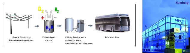
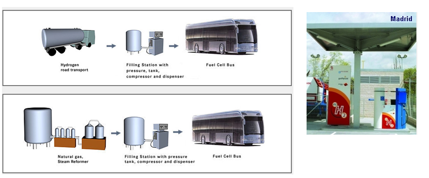
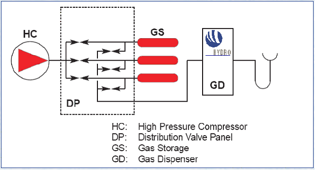
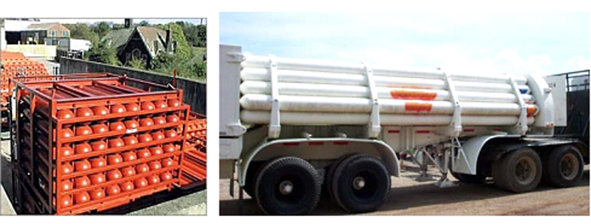
A 3D drawing illustrating the main system components at the refuelling station at Iceland in the ECTOS project is illustrated in figure 1. Below 2 hydrogen refuelling stations from the CUTE project are described. CUTE station in Hamburg The concept in Hamburg is illustrated below in figure 2. At the Hamburg station hydrogen is produced on-site by electrolysis using electricity The filling station and production facilities are located at HOCHBAHN's bus depot in Hamburg Hummelsbüttel. Using electricity from the grid and combining this with the production from certified green electricity for the hydrogen production on-site is fulfilling all goals of ecology and sustainability. A pressurised electrolyser (15 bar) produces high purity hydrogen with high efficiency which is then compressed to 450 bar and stored in on-site storage tanks. Busses can be filled up with 40 kg of hydrogen in 10 minutes which enables them to operate up to a range of 250 -300 km. CUTE station in Madrid At the station in Madrid there are two options for hydrogen supply: on-site production by natural gas reforming and gaseous hydrogen.delivered by truck. The concept is illustrated in figure 3. Hydrogen is delivered by 200 bar by tube trailers. Each one of them contains 3960 Nm3, composed of 264 small cylinders (85 liters) with hydrogen compatible with fuel cell requirements. Gas compression from these tube trailers to the bus is done by a water cooled membrane compressor. In Madrid Hydrogen is also produced on-site by a natural gas steam reforming process. An example of a principal sketch of a refuelling station concept downstream the production or supply unit is shown in figure 4. Compression The produced hydrogen, after being dried and purified, is compressed to about 450 bar (typical for the CUTE stations). The compressor(s) are usually located within an enclosure. Buffer storage Hydrogen is accumulated in high-pressure buffer vessels for fast transfer by pressure difference to the vehicle tank.. In order to minimize compression energy, the buffer is made up of multiple storage banks at different pressures, with the gas being taken first from the lower pressure bank (this pressure being sufficient to transfer product to the vehicle storage at initially low pressure) and then successively from pressure banks of increasing pressure. This is referred to as cascade refuelling further described hereafter. Maximum buffer storage pressure of 440 bar is typically required to refuell vehicles with 350 bar storage, in order to account for the temperature increase in the vehicle storage due to the fast filling. 700 bar refuelling requires 880 bar buffer storage. Dispenser/refuelling The description below for the refuelling system is based on cascade filling and high pressure storage. There may also be other alternatives. The Fuel Gas Dispenser is usually a "stand-alone" unit, which provides the mechanical interface between the hydrogen fuel station storage tanks and the vehicle, together with safety features and metering equipment. The dispenser consists of a small enclosure where regulation and control valves are located. The principle of cascade filling can be explained for a 3 cascades concept as follows: The vehicles will start to fill from the low pressure bank. When the pressure in storage tank and vehicle tank is balanced, the filling will automatically continue from the next cascade, medium pressure bank. Finally, the filling will be completed by topping up the vehicle tanks from the high pressure bank. This process is usually fully automatic. A two stage cascade filling system combined with a booster compressor, or a multiple stage cascade filling system with more than three pressure banks are other options. This is to ensure that the on-board vehicle storage tank reaches the appropriate fill pressure within the required time. The compressed gas hydrogen dispenser usually has a vent stack line to the atmosphere. Purging system Inert gas purging systems, which can be initiated automatically or manually are important ancillary parts of the filling station. Inert gas purging systems may be used during start up and shutdown and in emergency situations. Manning Future hydrogen filling stations, including the Hydrogen production unit, may be fully automated and can be unattended, with remote supervision.. In case of deviations from normal operation conditions, the system is designed so that it will shut down to safe conditions automatically. Shutdown can also be initiated by pressing emergency buttons at the filling station area or from a remote location. In the CUTE project , the stations were designed for refuelling of 3 buses per day, which corresponds to a production capacity of 60 Nm3/h. Most stations in demonstration projects are only able to refuel a few vehicles (buses or cars) per day, and there is still a long way to go to achieve the same capacity as for petrol and gasoline stations. The reasons are challenges related to storage capacity (available area and volume), safety (high pressures) and the requirement for short refuelling durations. For overnight refuelling the technical requirements are less challenging. Most existing hydrogen refuelling stations are part of demonstration projects, and, so far, all require that the users receive proper education and training with regard to the safety related properties of hydrogen and the vehicle refuelling process. The refuelling technology is new and not fully mature, very high storage pressures are necessary to obtain the desired autonomy, and gaseous fuels still are quite uncommon in most countries. However, experience from the demonstration projects will allow improve the technology, as well as the public’s “familiarity” with new types of fuels. Hydrogen used in clean vehicles running with a fuel cell or an internal combustion engine can be stored on board in liquid form at – 253°C at a pressure between one and ten bar. This type of storage allows a high energy density. It is then possible to store about 11 kg of hydrogen in a total storage of 75 kg and to use free form shapes (not only cylindrical) in the last generations of tanks made by Air Liquide. This storage mode involves a liquid distribution network from the hydrogen liquefaction plants to the on board tanks with tube trailers of 45 000 litres capacity (about 3 tons of hydrogen). Liquid hydrogen is delivered to onsite storage vessels (buried or above ground), and then distributed to the vehicles at the hydrogen refuelling station, either by pressure difference or by the mean of a liquid hydrogen circulation pump. When hydrogen is transferred by pressure difference, it is necessary to pressurize the source tank without heating in order to put the hydrogen in a subcooled state, allowing to avoid product vaporization in the transfer lines. Therefore, in case of a large source tank, this transfer mode involves the consumption of pressurization gas to make the transfer because the tank has to be depressurised between each transfer to avoid temperature increase of the hydrogen. This drawback can be managed by installing a buffer tank dedicated to pressurization between the source tank and the vehicle. In this case, filling of this tank is made at low pressure between two vehicle refillings, and only the buffer tank is pressurized to make the transfer. The other transfer method of cryogenic liquid is to install a transfer pump, which allows circulation of liquid and subcooling. This method allows to fill the vehicle tanks without having to significantly increase the pressure of the source tank. The drawback is that a machine has to be used. This equipment transfers heat to the fluid and must be periodically inspected. With the two methods, during transfer, a significant percentage of liquid hydrogen is used to cool down (or to compensate the heat losses of the lines) the lines and on board tank. This liquid hydrogen is therefore evaporated and sent back to the station through the vehicle connection. This hydrogen can be either reliquefied, vented to the atmosphere or compressed and sent to a compressed gaseous storage to be further used in a compressed gaseous refuelling station. Those two methods are currently used in liquid Hydrogen stations in demonstration projects. The choice between the two technologies is based on the following criteria :
Safety ChallengesThe safety challenges result not only from the implementation of hydrogen technology for use directly by the public in a non-industrial context and for a completely new application. It lies also in the demanding performance and cost targets imposed by the applications leading to:
The safety challenge is hence two-fold: 1. Address the known risks (e.g. H2 leak) in a way that is compatible with the operation of a public fuelling station: the conventional methods used by industry (large clearance distances, personnel protective equipment…) are not easily applicable here; 2. Discover and address all the new risk factors brought in by the new elements above and their combination. The fact that multiple actors are involved (cylinder and accessory manufacturers, vehicle manufacturers, refuelling station designers and operators, industrial gas companies...) further underlines this challenge. More specifically the challenges include:
Prior to generalization/public use of such stations, further work is needed to
Hydrogen ApplicationsIntroductionHydrogen applications, or end-use technologies, can be grouped by sectors:
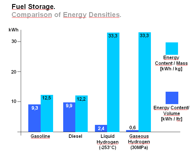
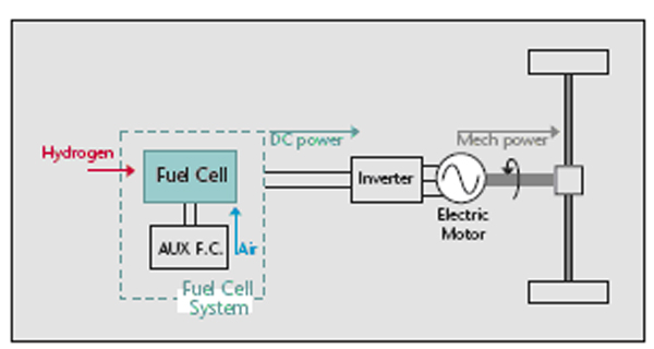
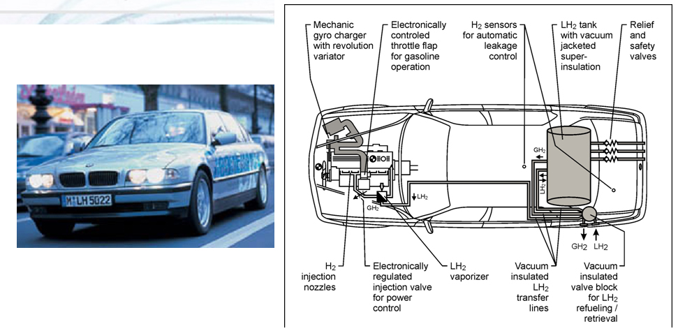
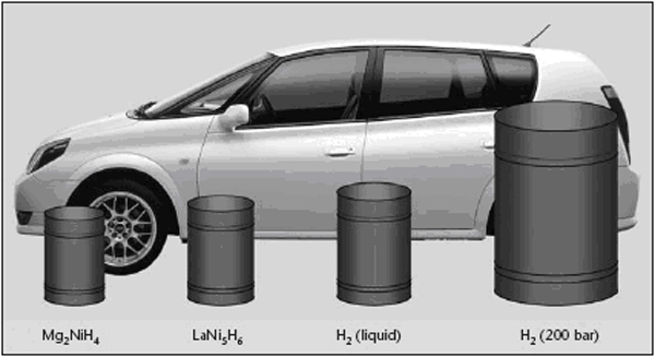
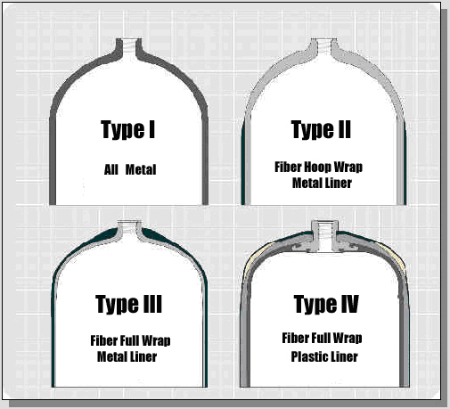
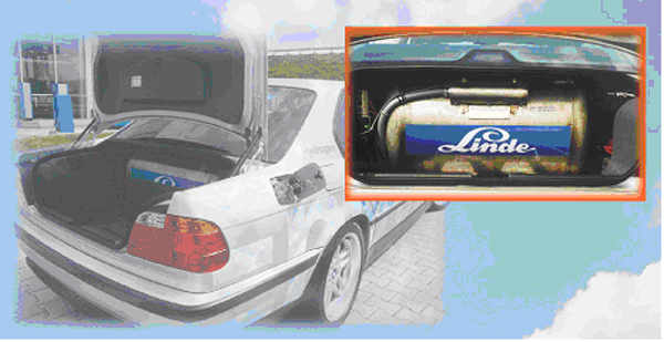
Transport applications, especially cars and buses, seem to be of highest priority but due to stringent performance and cost targtes, significant market penetration is not likely to occur before two decades. Stationary applications are not believed to play a relevant role for the hydrogen energy consumption in Europe before 2020 neither. However there could be significant development of niche markets in transport, stationary, and portable applications, which would positively contribute to further technological progress and public acceptance, despite their marginal impact on the total energy use. Hydrogen can be used to power vehicles my means of internal combustion engines (ICEs), fuel cells (FC) or gas turbines. FCs have a higher useful energy conversion efficiency than simple ICEs and they are therefore often used in automotive applications. ICEs are, however, well established technology that is relatively easy to convert from conventional liquid fuels to hydrogen, so some car manufacturers are also working on ICEs specifically for hydrogen. Gas turbines are today much too large to be used in road vehicles, but there are R&D development in countries including Germany and the USA aiming at developing smaller units, which when used with other energy conversion technologies in hybrid cycles, might improve the effectiveness (RisoEnergyReport:3:2004). Like any vehicle the driving range of a hydrogen vehicle depends on the amount of fuel, in this case hydrogen, that it can carry. Hydrogen has a lower volumetric energy content, especially in the gas phase, than conventional fuels such as gasoline, and storage of hydrogen on the vehicle is therefore a challenge. The storage system itself also includes a considerable weight and volume – thick walled vessels needed for gaseous high pressure storage (pressure 250 – 700 bar) or insulation and a boil-off management system for storage of liquefied hydrogen at cryogenic temperatures, see also figure 1. Several large R&D projects are in progress to solve these challenges and to address alternative solid storage techniques, e.g. metal hydrides. The low volumetric energy content and the limited infrastructure for hydrogen refuelling has also encouraged vehicle manufacturers to study the use of more conventional liquid fuels (e.g gasoline and methanol) that can be converted to hydrogen-rich gas mixtures by a “fuel processor” in the vehicle. However, it seems as if most vehicle manufacturers today focus on direct use of hydrogen for propulsion, and for most projects gaseous hydrogen is used instead of liquid hydrogen. Fuel processing may have a more significant role to play as auxiliary power units (APU) in, for example trucks. For on-board reforming in Fuel cell vehicles, methanol has been considered because it operates at lower temperatures and is more tolerant to intermittent demand. Gasoline or LPG reforming would even be more practical, since this infrastructure is already existing and could allow the introduction of respective vehicles even at a lower number. R&D activity on on-board reforming for passenger vehicles has significantly diminished in consideration of the intrinsic complexity and cost compared to the limited impact on CO2 emissions compared to direct use of hydrogen. Still on laboratory scale, but highly promising is the OTM (Oxygen Transport Memebrane) technology. References: Riso National Laboratory (2004) Riso Energy Report 3. {\tt http://www.risoe.dk/rispubl/energy\_report3/ris\-r\-1469.pdf}.(BibTeX) Examples showing a FC and a ICE vehicle are given below. A FC vehicle is illustrated by a Nissan X-Trail Fuel Cell Vehicle (figure 2) and an ICE vehicle by a BMW 750h (figure 3). At the core of the X-Trail FCV is the Nissan-exclusive Super Motor. In an ordinary motor, a rotor fitted with permanent magnets rotates around electromagnets (stator) to generate power that is output through one shaft. The Super Motor incorporates a new technique of applying compound current to the electromagnets and has two rotors positioned both on the inside and outside of one stator, allowing power to be delivered through two shafts. The Super Motor can achieve improvements in compactness and efficiency compared with the use of two motors. Additionally, it controls the power of each shaft separately, making it possible to drive right and left independently, enhancing dynamic performance and stability. One motor package also incorporates the dual functions of a motor and a generator. The Super Motor can be utilized in a wide variety of applications, including on fuel cell vehicles and hybrid vehicles, which benefit from the use of its generator function. Powering the Super Motor are high-output lithium-ion batteries that utilize a laminated lithium-ion cell in place of the conventional cylindrical shape. The use of a laminated cell as an automobile battery, which has a high current rate, requires larger terminals. The sealing performance of the cell also becomes an issue because of the gas produced by repeating charging and discharging cycles. BMW focus their development solely on ICE driven vehicles fuelled by liquid hydrogen. According to BMW an evolution of the existing ICE technology offers much better power density and propulsion efficiency as compared to fuel cells. One example of a BMW hydrogen vehicle, the 750h, is shown in figure 3. The 750h is powered by a 5.4-liter V12, featuring bi-VANOS variable valve timing, Valvetronic variable intake runners, and a fully variable intake manifold. The 750h can use either hydrogen or premium unleaded gasoline. Running on hydrogen, the 750h produces 150kW/200hp and can achieve a top speed of 215 km/h. The cruising range is 300 km. Added to the 640 km range of the normal fuel tank, the 750h can go 960 km between fill-ups. An Auxiliary Power Unit (APU) runs the 750h's power-consuming features. The APU operates on a 5kW Polymer Electrolyte Membrane (PEM) fuel cell that is independent of the engine, thanks to a direct hydrogen feed from the trunk-mounted tank. This means power accessories like air conditioning can be operated when the engine is shut off, saving 3.78 l of gas for every 280 km of city driving. BMW has announced that they expect a wide market entry not before 2010. The development of FC powered cars by other manufacturers such as DaimlerChrysler, Ford, GM/Opel, Toyota, Honda and Nissan has also led to a number of prototype vehicles on the road in Europe, Japan and the U.S. The complexity of hydrogen drive-systems is viewed as medium for the technologies both for the FC and ICE. If on-board reforming from hydrogen containing carbon based fuels is preferred, the system complexity rises due to the complex processing hardware involved which is required for the highly dynamic operating conditions. The technical maturity of both ICE and FC (without on-board reforming) for cars is judged as medium by the car industry as prototype vehicles are on the roads and field tests in the hundreds are imminent. Technical and economic challenges remain to be solved. For FC drive systems these are cost reduction by e.g. minimization of catalyst demand, material development towards e.g. high temperature membranes, extended driving range, storage system integration, further improvement of the onboard fuel reforming technology, cold start performance and reliability/operating life. For ICE vehicles improved fuel injection systems utilizing the refrigeration energy of liquid hydrogen and the hydrogen-mono-fuel performance have to be optimized. References: Invalid BibTex Entry!
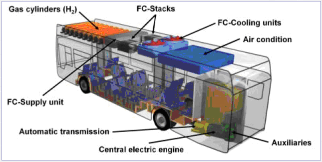
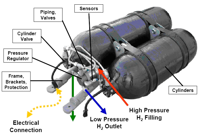
These arguments foster the use of hydrogen and specifically fuel cell operated city buses even though improvement potentials for high efficiency conventional diesel-engines are within reach. A number of prototype ICE and FC powered buses have been built and demonstrated in field tests throughout Europe. In the large European demonstration project, CUTE, 30 hydrogen operated fuel cell buses are test-driven in 9 European cities. A technical drawing showing CUTE fuel cell Citaro buses are shown in figure 2. To store hydrogen on board the CUTE buses, new generation hydrogen storage vessels are used operating at a pressure of 350 bar. Experiences collected with high pressure storage modules by Evobus during the design of natural gas buses contributed to the structural layout of the hydrogen bus. The storage module consists of 9 cylinders each containing 205 litres of geometrical volume. The carbon fibre-wrapped aluminium-lined (Type 3) tanks can contain a total of 44 kg of hydrogen at a nominal pressure of 350 bar. The quantity of hydrogen fuel that can be stored in the cylinders at one time is deemed sufficient for the typical daily range requirements of city transit buses. The hydrogen components are located on the roof of the bus. There are considered to be several advantages with this localization;
The fuel cell stack modules transform the chemical energy contained in the hydrogen fuel into electrical energy used to power the bus. The direct current from the fuel cells is regulated by an electrical inverter, which creates the alternating current to power the central traction engine. This engine is designed for a maximum power of 205 kW which is sufficient to give the fuel cell bus a similar driving and acceleration behaviour as a diesel bus. All other components required for the operation of the bus. e.g. 24 volts supply, air condition compressor, air compressor or steering wheel pump are driven by this central engine. The technical maturity for hydrogen buses is judged as medium with field tests in the hundreds in discussion such that – in combination with the simple and cost efficient refueling – a market entry is possible even before 2010. However, costs remains a significant barrier to deeper market penetration. TransportOther transport applications include:
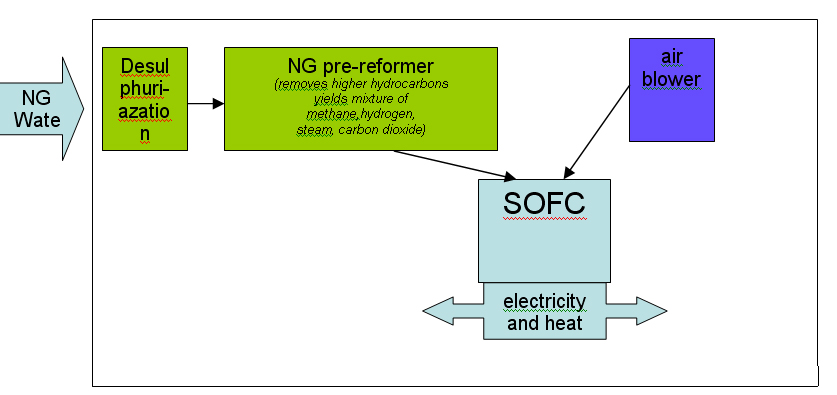
StationaryThe previous chapter was dealing with mobile applications for a hydrogen economy including the necessary stationary applications to build an infrastructure to make these mobile applications feasible like hydrogen refueling facilities. The application of hydrogen driven fuel cells are also thought to be valuable in other stationary applications e.g. in households. Field tests are being performed in several countries e.g. in Germany and Norway to show the feasibility of a combined electrical power and heat supply for households utilizing e.g. PEM or SOFC fuel cells. While in mobile systems PEM cells working at low temperatures -e.g. giving fast start up times - are the most suitable solution presently, stationary systems may benefit from high temperature type fuel cells as e.g. the SOFC (solid-oxide fuel cell) systems. These are working at about 700 to 900O C and have the advantage of being less sensitive on impurities in the supplied hydrogen and being able to internally convert natural gas and other fuels. (see figure 1 and 2) (PalssonJ:2003). The higher operating temperature is in the stationary application considered as an advantage as it makes the utilization of the waste heat easier. Fuel cell (e.g. SOFC) cannot only provide electrical power, but also can work in an inversed mode as electrolysers producing hydrogen, see also chapter 1.3.2.2. This potential flexibility would be important for a future strategy of decentralized electrical power supply, as this flexibility will help stabilizing the demand of electrical power. The role would be to act as a “power station” for periods with large demands of electricity and as a “consumer of electricity” for periods of excess production of electricity, e.g. in wind power systems. In such future systems the natural gas supply grid would be connected with the electrical power grid. It also would make it possible to establishing private hydrogen refilling stations e.g. for overnight refilling of the family car. For economic reasons, a wide hydrogen supply infrastructure for industrial or residential applications is not expected to be in place in the foreseeable future. Until a suitable hydrogen supply infrastructure is developed, fuel cells for industrial and residential use will typically be fuelled through conversion to hydrogen of natural gas, LPG or methanol. According to the Hynet report this technology has an expected market entry of between 2006 and 2008. Stationary applications can be divided in
and the general design of a fuel cell power system as described in the (IEC:TC105:2005) draft standard on stationary fuel cell systems (working group 3) shall form an assembly of integrated systems, as necessary, intended to perform designated functions, as follows:
coverts, typically, hydrogen rich gas and air reactants to dc power, heat, water and other by-products.
Most of the technologies (electrolysers, fuel cells, instrumentation, storage, compressors) are currently available or developed for commercialisation for operation with i.e. natural gas. Although several hydrogen specific end-use technologies such as gas turbines, internal combustion engines and also Stirling engines exist, fuel cells are believed to have the best chance for widespread commercialisation in stationary hydrogen energy systems as they provide highest efficiencies and a number of other structural advantages. For specific tasks such as compression for pipeline transport, gas turbines or during the transition phase towards a wide hydrogen use, gas internal combustion engines can become viable options. 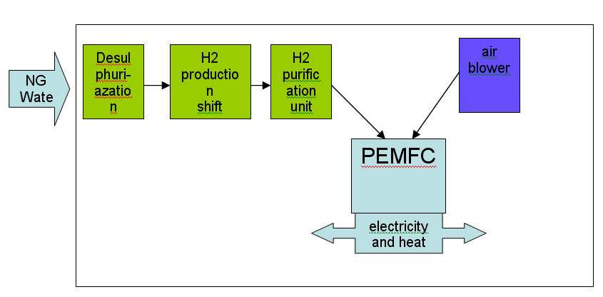 Figure 2: Principal of NG reforming utilizing PEMFC (see ([[http://hysafe.net/wiki/BRHS/OFD-Chapter2?action=bibentry&bibfile=DB&bibref=PalssonJ:2003 | PalssonJ:2003 Δ))]] However, the future use of hydrogen entering the stationary market as a viable fuel will be dictated by infrastructure. It is expected that in the longer term, i.e. after 2020, a hydrogen infrastructure for stationary applications could develop. The success of this will depend on a number of factors including the degree of decentralization in stationary energy markets, energy demand reduction, the need for load leveling capabilities for renewable energy and the success of competing technologies such as combining a hydrogen admixture to the natural gas in the existing grid. Additionally carbon capture schemes for large-scale centralized power generation could be based in the future on natural gas reforming or fossil fuel gasification technologies, with large scale production of hydrogen and its consumption in efficient combined cycle gas turbine (CCGT) schemes. These different options will have to be tested, with lighthouse demonstration projects being a viable way of achieving this. A current limiting step in these demonstration projects is the lack of small reformers for fuel cells in the 1 - 10 kWel class. A possible means of bridging this technology gap could be to use local hydrogen distribution grids fed with hydrogen from either commercially available central reformers, electrolysers or from by-product hydrogen. In this way, a hydrogen infrastructure for stationary supply would evolve from local clusters. It is not expected that the direct use of hydrogen to provide power for industrial or residential use will play an important role in the short-medium term. However, longer term, an increasing amount of hydrogen for use as an energy buffer may be required. The development of the necessary infrastructure will have to be adapted to the changing needs of the evolving decentralized energy markets. It will likely start with local and virtual hydrogen supply islands. References IEC-TC-105 (2005) Fuel Cell Technologies - Part 3-3: Stationary Fuel Cell Power Plants - Installation..(BibTeX)
micro fuel cells The main market fuel cell based portable batteries are mobile phones, personal digital assistants (PDAs), laptop and notebook computers, cameras, medical equipment, military applications and other portable electronic devices. In comparison to batteries, fuel cells can supply much more power per unit volume or weight and also give the ability to retaure power by simply replacing the fuel cartdrige. However, they have lower output voltages and are slower to respond to transients. DMFCs are mostly used for small units and devices in integrated systems because they use a liquid fuel with a high energy density that is easy to distribute. PEMFCs for portable generators do not differ much from the large PEMFCs used in stationary and transport applications. However, PEMFCs that are to be integrated into small electronic devices, need to be specially designed for miniaturisation. Fuel cells for portable applications have the advantage that the cost per kW is much less important (not a barrier to market introduction) than for stationary and transport applications. They are usually only required to have relatively short lifetimes, typically of the order 2,000 hours. This makes them suitable for rapid market introduction. Fuel cells do not create new applications for portable equipment, but they can improve the practical value of existing devices. As battery replacements, for instance, fuel cells can increase the operating time of electronic and electrical equipment. Illustrations of portable applications are shown in figures 1 - 2 below (RisoEnergyReport:3:2004): portable generators For fuel cells up to 5 kW, main market includes portable generators, uninterruptible power supplies (UPSs), auxiliary power units, power tools, light vehicles such as electric trolleys, lawn mowers and roadside equipment. In comparaison with conventional ICE generators, fuel cell portable genrators offer lower noise and exhaust emissions. In this marked sector it is necessary to solve the remaining problems associated with reliability and lifetime. References: Exploiting Synergies between End-use SectorsWhen developing an infrastructure to support these applications, it would make sense to exploit any synergies between the sectors - transport, stationary and portable. One such example is the concept of an energy station, combining power generation and hydrogen refueling at the same location. This could provide the means to manage the utilization rate of refueling sites, particularly in the early stages of vehicle introduction when demand will be limited. Such an energy station could help to establish local stationary hydrogen energy clusters for small industrial or residential use. Hydrogen can also play a role in managing the intermittence of renewable power generation from technologies such as wind and PV (both in grid connected and off-grid schemes). One example is the demonstration project at the Norwegian Iceland Utsira, where 10 households receives electricity solely from wind turbines and hydrogen. This is conceptually similar to energy storage schemes for managing peak and off-peak supply/demand imbalances, using compressed air plants or pumped-hydro-storage. However, these current installations are insufficient for load-managing large amounts of future renewable generation. It has therefore been proposed to use the surplus electricity to generate hydrogen via electrolysis and use the hydrogen as daily and/or seasonal storage. In addition, this hydrogen could also be employed as a vehicle fuel. One can also envisage that hydrogen fuel cell vehicles could be used to supply electricity (and heat) to residential, office buildings or recreational areas, while parked during working hours. Another option could be the establishment of cylinder-filling points at refuelling stations. Such filling points would serve as an infrastructure for portable fuel cell applications in industrial, household and recreational use. The convergence of the sectors to a common fuel provides the opportunity to improve the economics of hydrogen distribution and supply by developing such innovative approaches to optimise the use of these novel energy conversion devices. EU projects within Hydrogen applicationsLists of EU financed projects focused on hydrogen applications from 2002 – 2006 are given below. The topic adressed within each project is also given. The lists and additional information can be found in the report of `European Fuel Cell and Hydrogen Projects, (EuropeanCommission:EUR22398EN:2006). References {European Commission, Directorate-General for Research, Directorate-General for Energy and Transport} (2006) European fuel cell and hydrogen projects. RTD Info, EUR 22398 EN, Brussels.(BibTeX) Hydrogen Systems Main ComponentsOnce hydrogen has been produced, several steps are usually necessary to transport and/or liquefy/compress the gas before it can be sent to the end-user for storage or use. Below a short description of main components, which are often needed in this process. CompressorsCompressors Raising the hydrogen gas pressure for its storage (150 bar to 300 bar in industrial applications, currently up to 700 for vehicle applications) or transportation in pipelines (typically 100 bars) is achieved with volumetric compressors. Either piston or diaphragm compressors are used. The latter type is often preferred because it fully preserves the products purity and requires little maintenance. Two examples of hydrogen compressors are shown in figure 1 and 2. Multi-stage piston compressors are more effective when the ratio between outlet and inlet pressure is large. This is typically the case when the inlet pressure is very low (a few bars or less). If the piston is oil lubricated, an oil removal system is necessary. For small and intermittent hydrogen flows such as those encountered at the end of a vehicle tank refuelling cycle (when pressure is maximum), compressed air driven reciprocating compressor are sometimes chosen for reasons of simplicity and compactness. In fuelling station applications, a combination of compression technologies may be used to perform the various compression steps necessary, taking into account operating time and duty cycle in order to minimize total ownership costs. Thermal compression Compressing hydrogen to 700 bar by the means presented above requires application of mechanical energy representing approximately 10% of the gas’ energy content. Thermal hydride hydrogen compression is a means to compress hydrogen by applying only heat. In the thermal compressor, hydrogen is absorbed in a reversible metal hydride alloy at low pressure in a water-cooled container. The container is subsequently heated with hot water, which releases the hydrogen at higher pressure. Continuous compression is achieved with two identical containers in a parallel configuration; one container is cooled by water and absorbs hydrogen until it is full, while the other container is heated with hot water in order to release hydrogen at the same rate. The cool and hot water streams are periodically switched and simple check valves keep hydrogen moving through the thermal compressor. By employing successively higher pressure hydride alloy stages in series, high pressure ratios can be generated. Hydride compressors are compact and silent. When powered by waste heat, energy consumption cost is only a fraction of that required for mechanical compression. However, thermal compression of hydrogen using metal hydrides requires pure hydrogen streams that typically have less than 50 ppm of active gas impurities, as impurities can react with the hydride alloy and reduce its hydrogen storage capacity and/or impede the absorption of hydrogen. Flow rate is limited by heat transfer limitations associated with large alloy beds. Indeed, when metal hydride alloys absorb hydrogen, the chemical reaction is exothermic and heat is generated. This heat must be removed from the alloy in order to continue the absorption process to completion. Likewise, the alloy must be heated to release hydrogen. The rate of hydrogen throughput depends upon the speed that heat can be transferred into or away from the alloy. Improving heat transfer rate increases hydrogen throughput. Hydride compressors built to date have flow rates not exceeding a few tens of Nm3/h. Design safety considerations specific to hydrogen service in addition to those generally considered for gas compressing systems are indicated below : Materials The compressor must be designed with particular reference to hydrogen service. In particular all metallic material wetted by pressurized hydrogen must be suitable for hydrogen, i.e. not susceptible to hydrogen embrittlement unless used at low enough stress or without consequence on safety in case of failure. Prevention of ingress of air at inlet To avoid a vacuum in the inlet line and consequent ingress of air in the event hydrogen feed is closed off , the inlet pressure needs to be monitored with automatic compressor shut-down before this pressure drops below ambient pressure. Monitoring of oxygen content at inlet Where the hydrogen comes from a low-pressure source, or where there is a possibility of oxygen contamination, the oxygen content needs to be monitored with automatic compressor shut-down if the oxygen content exceeds 1%. Discharge temperature control As they may put at risk vital functions of process equipment, situations of excessive compressor discharge temperature, must be detected with immediate corrective actions such as compressor shut-down. Prevention of hydrogen-air mixtures in internal volumes Absence of air in internal volumes to which hydrogen may leak, such as the crank-case, needs to be ensured, for instance by pressurisation (with hydrogen or nitrogen). Over-pressure relief from internal hydrogen leaks The vents of pressure relief devices protecting secondary circuits such as a closed water cooling circuit or the crank case against overpressure arising from a leak from the hydrogen side need to be arranged so that their discharge will not generate a dangerous situation. Regarding compressed H2 purity, contamination risks originating from the compressor need to be considered. With oil lubricated piston compressors, oil contamination can result from malfunction of the oil removal system. With diaphragm compressors there is the potential of product contamination by hydraulic oil in case of diaphragm failure. This is typically prevented by using double or multi-layer diaphragm constructions with a leak detection system. The compressor’s cooling water circuit is another potential source of contamination which needs to be considered closely especially for vehicle fuelling application, considering that such water contamination may have adverse effects on the vehicle’s on-board storage if its liner is made of a material sensitive to stress corrosion. This is often the case for the grades of aluminium typically used in such applications. References HOFER (2006) Dry-running HOFER piston compressors for hydrogen application with hydraulic drive unit, type TKH..(BibTeX) Linde-Hampson Process The Linde-Hampson method is a thermodynamic process, where isothermal compreesion and subsequent isobaric cooling is done in a heat exchanger. Joule-Thompson expansion connected with an irreversible change in entropy is used as the refrigeration process. Despite its simplicity and reliability, this method has become less attractive compared to modern ones, where cooling is carried out in reversible processes (expander) at reduced energy consumption. Claude Process A commonly applied method in large-scale liquefaction plants is the Claude process, where the necessary refrigeration is provided in four main steps 1. Compression of hydrogen gas, removal of compression heat; 2. Precooling with liquid nitrogen (80 K); 3. Cooling of a part of the hydrogen in an expander (30 K) 4. Expanding of the residual hydrogen in a Joule-Thompson valve (20 K) Joule-Thompson expansion is applied for the final step to avoid two-phase flow in the expander. Further improvement in efficiency is expected with the development of new materials and new compression/expansion technology. Magnetic Refrigeration Process A qualitatively new approach is the magnetic refrigeration process takes advantage of the entropy difference and the adiabatic temperature change upon application or removal of magnetic fields in the working material. It uses isentropic demagnetization of a ferromagnetic material as cooling process. It is expected that 15 separate cooling stages are necessary for hydrogen o get down to the boiling point. This method is still on an R&D level, but it appears promising because of its compact cooling device with long lifetime, low capital investment, and higher efficiency with an estimated liquefaction work of 7.3 kWh/kg. Storage - IntroductionStorage is a challenging issue that cuts across production, delivery and end-use applications of hydrogen as energy carrier. Storage constitutes a key enabling technology for the hydrogen economy, as a main appeal of hydrogen, compared to the already established clean energy vector electricity, is that it is more readily stored and transferred. Hydrogen storage systems will thus be present in both stationary and mobile or portable applications. There are several “storage options” to choose from: gaseous, liquid, “solid-state” and other novel media. Figures 1 and 2 illustrate the gravimetric and volumetric densities achieved or expected for the various storage options in on-board vehicle applications. References: {European Hydrogen and Fuel Cell Technology Platform. Implementation Panel} (2005) Strategic Research Agenda..(BibTeX) Storage - Gaseous HydrogenCompressed gaseous hydrogen (CGH2) storage is used both in stationary and in mobile applications. Examples of storage systems for stationary applications are conventional 50-liters steel bottle bundles, tube trailers or fixed tube bundles (CastelloP:2005)(figure 1). The term “conventional” refers to the fact that these bottle/tube systems are a proven technology based on the use of mainly steel as structural material and involving gas pressures up to 230 bar. These systems are used essentially at industrial chemical/metallurgical plants and distribution centres, such as fuelling stations or cylinder filling centres, sites along pipelines, hydrogen production sites associated with offshore wind parks or stationary power applications. As stated in the Strategic Research Agenda of the European Hydrogen & Fuel Cell Technology Platform, “underground and underwater storage facilities are considered to be of strategic importance to match hydrogen production and demand and to ensure energy reliability. Their deployment depends more on regulatory approval than on further research.” (HFP:StrategicResearchAgenda:2005). Concerning mobile applications, high-pressure CGH2 storage is being actively researched since the early nineties. The idea of fuelling road vehicles with hydrogen has driven the development of lightweight and highly resistant tanks made of composite materials to store the gas at up to 700 bar. CGH2 tanks for vehicles can be classified in four types (see EN ISO 11439:2000) as showed in figures 2 and 3: The tanks used in vehicles are type III and type IV. The targets set by the Strategic Research Agenda are (vehicle range of 500 to 600 km): 5 kg of storage at 700 bar (~120 @ 20şC), with H2 delivery temperatures between -40şC and +85şC and a lifetime of at least 1,500 cycles. Vehicle tanks are fitted with various safety and monitoring-related components (figures. 4 and 5). References: Castello P. and Salyk O. (2005) Testing of Hydrogen Safety Sensors in Service Simulated Conditions. Paper presented at the First International Conference on Hydrogen Safety, Pisa, Italy.(BibTeX) Storage - Liquid HydrogenHydrogen in liquid form has a considerably higher energy density than in its gaseous form, making it an attractive storage medium (Figure 1). This hydrogen storage technology is rather effective but has disadvantages, mainly the energy required to liquefy the gas and the strict control needed on the container temperature stability to avoid any risk of overpressure. It also requires cryogenic vessels and suffers from hydrogen losses through evaporation from the containers (boil-off). The cryogenic vessels used to store liquid hydrogen on-board vehicles, sometimes also called cryostats, are metallic double-walled vessels with a high vacuum or material insulation, sandwiched between the walls. References: [DB,StoecklinM:2002] Storage - Metal HydridesSolid storage of hydrogen is possible with metal hydrides. Metal hydrides are chemical compounds of hydrogen and other material such as magnesium, nickel, copper, iron or titanium. Basically, hydrogen bonds easily with more than 80 metallic compounds, forming a weak attraction that stores hydrogen until heated. These so-called metal hydride systems can either be at low (< 150şC) or high temperature (300şC). Hydrogen can be stored in the form of hydrides at higher densities than by simple compression. However they still store little energy per unit weight. On the other hand, since heat is required to release the hydrogen, this method reduces safety concerns surrounding leakage that can be a problem with compressed hydrogen and LH2. However, as metal hydride material may react spontaneously when exposed to air or water, other specific safety issues need to be addressed. Metal hydrides begin as intermetallic compounds produced in much the same way as any other metal alloy. They exhibit one important difference. When metal hydrides are exposed to hydrogen at certain pressures and temperatures absorb large quantities of the gas and form metal hydride compounds.(PalcanMetalHydrides) When molecular hydrogen from the hydrogen gas comes into contact with the surface of a hydrogen storage metal hydride material, it dissociates into atomic hydrogen and distributes compactly throughout the metal lattice. Metal hydrides literally trap hydrogen within the alloy, much like a sponge absorbs water. When heat is applied, the gas is released. Absorption process Hydrogen gas molecules (H2) stick to the metal surface and break down into hydrogen atoms (H). The hydrogen atoms* then penetrate into the interior of the metal crystal to form a new solid substance called a "metal hydride". The metal atoms are usually stretched apart to accommodate the hydrogen atoms. The physical arrangement (structure) of the metal atoms may also change as the hydride forms. Desorption process Hydrogen atoms* migrate to the surface of the metal hydride, combine into hydrogen molecules (H2) and flow away as hydrogen gas. The metal atoms contract to form the original metal crystal structure.
Metal hydride compounds are thus formed, allowing for the absorption of hydrogen in the materials, while heat is simultaneously released in the process. Conversely, hydrogen is released (desorbed) when heat is applied to the materials. Hydrides can desorb the hydrogen at roughly the same pressure required for storage. In fact, the key to practical use of metal hydrides is their ability to both absorb and release the same quantity of hydrogen many times without deterioration. In chemical shorthand, a typical reaction for such reversible metal hydrides can be expressed as shown below where M represents the metal, H2 is hydrogen and MH is the metal hydride. M + H2 -> MH + Heat Out M + H2 -> MH + Heat In This reaction is reversible. By changing conditions, the reaction can be made to go in either the forward or reverse direction. Its direction is determined by the pressure of the hydrogen gas. If the pressure is above a certain level (the equilibrium pressure or “plateau pressure”), the reaction proceeds to the right to form a metal hydride (the metal absorbs hydrogen to form a metal hydride); if below the equilibrium pressure, hydrogen is liberated and the metal returns to its original state. The equilibrium pressure depends upon temperature as it increases with increasing temperature. The storage in metal hydrides requires an absorption and a desorption step, in which heat must be taken out from the material or fed to the material from the environment. The heat on the right-hand side indicates that heat or energy is released when the metal hydride is formed, and thus, heat must be put in to release hydrogen from the metal hydride phase. The heat is the enthalpy (heat of formation) of the reaction and is an indication of the strength of the metal-hydrogen bond in the metal hydride phase. The hydrogen absorbing behaviour of metal hydride alloys is characterized using equilibrium pressure-temperature-composition (PTC) data. This data is determined by keeping an alloy sample at constant temperature while precisely measuring the quantity of hydrogen absorbed and the pressure at which sorption occurs. The quantity of hydrogen absorbed is expressed in terms of alloy composition, either as an atomic ratio of hydrogen atoms to the number of atoms in the base metal alloy, or as the capacity of hydrogen in the alloy on a weight percent basis. Hydride alloys can be engineered to operate at different temperatures and pressures by modifying alloy composition and production techniques. Hydride absorption is accompanied by a heat of formation that is exothermic. In order to continuously absorb hydrogen to an alloy's maximum capacity, heat must be removed from an alloy bed. The rate at which a hydride alloy can absorb or release hydrogen is dependent upon the rate at which heat can be transferred into or out of the alloy. Increasing the heat transfer rate allows the processing of higher flow rates. To improve the performance of the storage systems based on metal hydrides, researchers must find ways to increase the proportion of hydrogen in the hydrides, whilst maintaining the reversibility of the reaction within a reasonable temperature and pressure range. Many alloys form hydrides with up to 9% Hydrogen but will release the gas only at extreme temperatures. [Nickel Institute] Today one class of metal hydride material is used in practical applications, the conventional low temperature hydrides. Other classes have been developed or are being developed: the high temperature Magnesium hydrides and the medium temperature Alanates. Low temperature hydrides release hydrogen at near ambient temperature and pressure (different groups of materials exist, based on Ti, Zr, V, Rare Earth or other compounds). Their reversible hydrogen storage density is usually between 1.5 to 1.8wt%. The high temperature metal hydrides are mainly based on Mg. These materials need operating temperatures above 230şC (260-280şC) to release the hydrogen. They are capable of theoretically storing about 7wt% with about 5-6 wt% being reached at lab scale today. A new class of metal hydrides, the so called medium temperature materials and particular the Alanates (e.g. NaAlH4, or LiAlH4) are currently being investigated with high expectations. Based on the use of light metals such as Mg and Al storage densities of 4.5 to 5.0 wt% at 130şC have been shown with the theoretical maximum being 5.5 wt% or 4.5 system wt%. However, reactivity of this medium to air, water or other fluids is a safety concern that remains to be addressed. Storage - Porous MediaPorous systems compared to gaseous and liquid media offer the advantage of lower pressure hydrogen storage, increased safety, design flexibility and reasonable volumetric storage efficiency (TzimasE:2003). However, the technology is not yet mature. Also, there are no imminent solutions for avoiding weight/cost penalties, and tackling thermal management issues associated with this option. The materials included in this category are:
Storage - OtherThere are also other hydrogen storage methods, such as the following ones, (TzimasE:2003): Glass microspheres Tiny hollow glass spheres can be used for safely storing hydrogen. These glass spheres are warmed, and their walls permeability is increasing. Then, they are filled by immersion in high-pressure hydrogen gas. Following this, the spheres are cooled down to room temperature and the hydrogen is trapped inside the glass balls. Subsequent increase in temperature releases the hydrogen locked in these spheres. Hydride slurries These are a pumpable mixture of fine, solid metal hydride particles and a liquid (usually a mineral oil). Hydrogen is stored as a metal hydride in slurry with an organic carrier. It can be released from the metal complex through chemical reactions. Boron Nitride Nanotubes These are roughly equivalent to carbon nanotubes in terms of advantages, but are based on boron nitride rather than carbon. Bulk Amorphous Materials (BAMs) These are promising metallic materials based on multicomponent alloy systems, e.g. Ti-Al-Fe based BAM (maximum 6wt.%). They are loosely packed with porous defects (interstitial holes for hydrogen storage) of controlled size and distribution, in super cooled liquid phase. Hydrogenated amorphous carbon These are composed of stressed graphitic “cages”/nanotube sponges able to store 6-7wt.% hydrogen, are rather stable at 300şC with a potential for high hydrogen content and alleged potential to rapidly release hydrogen between 200-300şC. Chemical storage media (boron hydrides, amines, methanol, ammonia etc.) The hydrogen is often found in stable chemical compounds and it can then be released by a reaction the exact nature of which depends on the type of storage compound. Hybrids The option of combining storage solutions to create systems possibly achieving increased storage capacities and/or reduced improved safety levels is known as ‘hybrids’ (for example: hydrides/high pressure, porous/hydrides hybrid systems). EU Projects projects within Hydrogen storage 2002Lists of EU financed projects focused on hydrogen storage from 2002 – 2006 are given below. The topic adressed within each project is also given. The lists and additional information can be found in the EC report (EuropeanCommission:EUR22398EN:2006). References: {European Commission, Directorate-General for Research, Directorate-General for Energy and Transport} (2006) European fuel cell and hydrogen projects. RTD Info, EUR 22398 EN, Brussels.(BibTeX) Anode Reaction: H2 —> 2 H+ + 2 e- Cathode Reaction: ˝ O2 + 2 H+ + 2 e- —> H2O The basic principles of a fuel cell are illustrated in figure 1 The design of fuel cell systems is complex and can vary significantly depending upon fuel cell type and application. However, most fuel cell systems consist of the following basic components:
Fuel cells are generally categorized by their electrolyte. This material's characteristics determine the optimal operating temperature and the fuel used to generate electricity, and as a result, the applications for which these cells are most suitable (transport, stationary power and portable power). Each comes with its particular set of benefits and shortcomings. The main types of fuel cells are the following ones: I would like to have more detailed descriptions of these fuel cell (stacks) understood as “components”, again this is much like a description of technology
Table 1 shows the comparison of the main fuel cell technologies: Concerning fuel cells’s technology challenges, cost, durability and reliability are the major challenges to their commercialization. However, and according to the application, system size, weight, and thermal and water management are also additional barriers to the commercialization of fuel cell technologies. Monitoring and Control ComponentsChemical and physical processes involving hydrogen ˇV like any hazardous materials - must be monitored to ensure that they are within specific control limits (safe operation window). Hydrogen production units and applications often require a rather complex control system, due to varying conditions and operation modes including significant dynamic operation. Examples of such conditions are given below
Hydrogen systems usually involve a considerable number of components, such as valves, pressure relief devices, pressure and temperature regulators, check valves, filters and instrumentation. These components are crucial for the safety of the system. The components in a hydrogen system must be fabricated of materials, including soft goods such as seats and seals, that are compatible with the operating conditions, and with each other if more than one material is involved. The control system consist of measuring instrumentation - monitoring equipment such as flow meters, pressure and temperature transmitters, which in case of unacceptable process deviations will give a signal. This signal might give alarms in control room, or may initiate the control system e.g. to close or open valves dependent on the situation. Instrumentation provides a means to communicate with physical processes to obtain quantitative measurements of the behaviour or the state of the process. Controls provide a means to maintain or change the behaviour or state of a process. These are essential elements of a hydrogen system both for operation and safety of the system. It is of outmost importance that adequate instrumentation is designed so that the operation is within safe and acceptable limits. Usually, when designing a hydrogen system a systematic analysis is carried out, to check out possible deviations from normal operating conditions. These deviations are identified by using keywords (high/low/no/reverse flow/pressure/temperature/ignition sources etc.). Causes and consequences of these deviations are identified, and in case a hazardous or otherwise unwanted consequence, systems for detection and control of the hazardous deviation are included in design of the system. Usually redundant systems are included for deviations that might lead to a hazardous situation. Below some examples are given related to control components and situations when they are necessary. It must be underlined that this is just a very limited number of examples, and are not at all representative for the whole number of components or situations. Examples of control components:
These components have to be approved for the environments/installations where they will be installed, e.g. by CE-marking in Europe. Also the operator/owner of the installation is obliged by various regulations to assure that the components are installed/used in accordance with theis speicifications and limitations. Remote control of unmanned installations located in a public environment set high requirements to the control system ˇV to material properties and safe and reliable function. These examples represent situations coupled to control of the "internal" process operation. In case of a hydrogen leak to atmosphere, additional systems might be necessary to lead the system to a safe condition. Examples of components and measures are gas detection, fire detection, emergency ventilation, deluge and sprinkling, explosion venting etc. These measures are described in chapter 5 on mitigation. Also in such situations a well designed process control system will bring the process to a so-called "fail-safe" condition, for example emergency shutdown of process, ventilation of hydrogen under pressure to a non-hazardous location and purging of process components with inert gas. << | Content | >> |