
|
BRHS /
Subsonic & sonic jetsGaseous hydrogen releases through a hole or a conduct are produced as a result of a positive pressure difference between a container and its environment. The aperture is often modeled as a nozzle. Depending on the upstream pressure, a flow through a convergent nozzle to a lower downstream pressure can either be chocked (or sonic) or subsonic. The crossover pressure is a function of the ratio of the constant volume to the constant pressure specific heat, see Hanna and Strimaitis (HannaSR:1989). The flow resulting from a subsonic release is basically an expanded jet. The concentration profile of hydrogen in this expanded jet is inversely proportional to the distance to the nozzle along the axis of the jet. At a given distance from the nozzle, the concentration profile of hydrogen in air is distributed according to a Gaussian function centered on the axis. The following formula has been suggested by Chen and Rodi (ChenCJ:1980) for the axial concentration (v/v) decay of variable density subsonic jets:
Where C(x) is the concentration (vol) at location x, Cj is the concentration at the outlet nozzle, dj is the jet discharge diameter, ρα is the density of the ambient air, ρg the density of the gas at ambient conditions, x is the distance from the nozzle along the jet axis, x0 is the virtual absicca of the hyperbolic decrease (usually neglected because it is of the order of magnitude as the real diameter) and K is a constant equal to 5. For hydrogen, chocked releases occur when the upstream pressure is 1.9 times larger than downstream, otherwise the flow is subsonic. The flow rate of a chocked flow is only a function of the upstream pressure, whereas the flow rate of a subsonic release will depend on the difference between the upstream and downstream pressures. A release from a compressed gas storage system into the environment will therefore be chocked as long as the storage pressure remains larger than 1.89 bars. A chocked release of hydrogen undergoes a pressure and a temperature drop at the exit of the nozzle. The pressure will drop until the exit pressure reaches the value of the downstream pressure. At that point, the release becomes subsonic and the exit pressure remains constant at the downstream value. In the chocked regime, the gas velocity at the exit of the nozzle is exactly the sonic velocity of the gas. The flow rate can therefore be estimated from
where ρ is the density of hydrogen at the exit of the nozzle, calculated using the local value of the temperature and the pressure. The flow rate will also be affected by the shape of the aperture, friction and the length of the conduit between the reservoir and the release point. Because the exit density changes as a function of temperature and pressure, and because the sonic velocity is essentially proportional to the square root of the temperature, the flow rate will not remain constant but will vary as the upstream pressure drops (Fig. 1). Figure 1 shows the effect of using real gas hydrogen properties compared to ideal gas. It is well known that at high storage pressures real hydrogen gas densities are lower than ideal gas densities. Table 1 compares real versus ideal hydrogen densities at temperature 288 K and pressures 200 and 700 bar, (values taken from the (MarshallN:1976) ). For given storage volume the real gas assumption results in less stored hydrogen mass and consequently less released mass in an accidental situation. Table 1: Comparison between real and ideal gas properties
The effect of real gas properties has been taken into account in the 1983 Stockholm hydrogen accident simulations by Venetsanos et al.(VenetsanosAG:2003), where tables from Encyclopedie des gaz were used to obtain the hydrogen density. Real gas properties calculations based on the Beattie–Bridgeman equation of state were reported by Mohamed and Paraschivoiu (MohamedK:2005) , who modeled a hydrogen release from a high pressure chamber. Real gas properties using the Abel-Nobel equation of state were considered by Cheng et al.(ChengZ:2005) who performed hydrogen release and dispersion calculations for a hydrogen release from a 400 bar tank through a 6 mm PRD opening and found that the ideal gas law overestimates the hydrogen release rates by up to 35% during the first 25 seconds after the release. Based on these findings these authors recommended a real gas equation of state to be used for high pressure PRD releases. 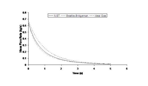 Fig. 1: Mass flow rate as a function of time from a 6 mm aperture of a 345 bar compressed gas 27.3 litre cylinder (calculated using the NIST (LemmonEW:2000) , the Bettie-Bridgeman and the ideal gas equations of state based on (MohamedK:2005). A chocked jet (Fig. 2) can be basically divided into an under-expanded region, where the flow becomes supersonic, forming a cone-like structure (the Mach cone) (Fig. 3); and an expanded region, which behaves similarly to an expanded subsonic jet. The under-expanded region is characterized by a complex shock wave pattern, involving bow and oblique shocks (Figs 3 and 4).  Fig. 2: Chocked release from a 150 litre 700 bar reservoir (AngersB:2006). 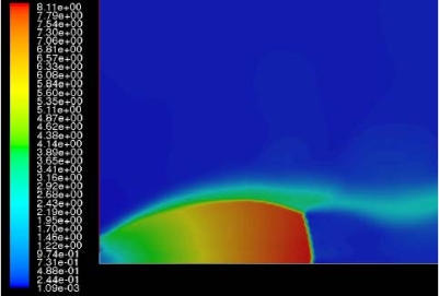 Fig. 3: Under-expanded chocked release of hydrogen (the Mach number is calculated with respect to air). 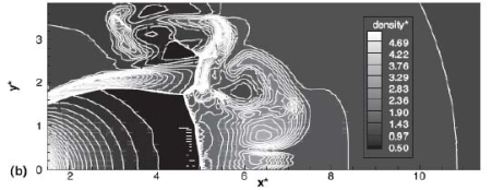 Fig. 4: Normalized density contours as a function of position (hydrogen jet in hydrogen atmosphere; source: (PedroG:2006) As for subsonic releases, the concentration profile of hydrogen in the expanded region is inversely proportional to the distance to the nozzle along the axis of the jet and is distributed according to a Gaussian function at a fixed distance from the nozzle. The axial concentration decay can be calculated using the formula for variable density subsonic jets, see Eq.(1), where the discharge diameter is replaced by the effective diameter, which is representatve of the jet diameter at the start of the subsonic region, i.e. after the Mach cone.
For the determination of the effective diameter various approaches have been proposed, such as (BirchAD:1984), (EwanBCR:1986) and (BirchAD:1987). In this latest approach, the effective diameter and corresponding effective velocity is calculated by applying the conservation of mass and momentum, between the outlet and a position beyond the Mach cone where pressure first becomes equal to the ambient, assuming no entrainment of ambient air.
Where ρj and uj are the density and the velocity of the jet at the outlet (respectively), ueff is the effective velocity, dj the diameter of the outlet. The effective velocity is calculated using the following expression:
where pj is the pressure of the jet at the outlet and pα is the ambient pressure. Regarding the constant K entering Eq.(3), different values have been reported in the literature. An average value of 4.9 is mentioned by Birch (BirchAD:1984) . An average value of 5.4 was reported in (BirchAD:1987) . This approach ((BirchAD:1984) and (BirchAD:1987) ; (HoufW:2005)) has been validated experimentally for vertical chocked releases for pressures below 70 bars for natural gas and hydrogen. A lower value K = 3.7 was reported by Ruffin (RuffinE:1996) who investigated experimentaly the concentration field of horizontal supercritical jets of methane and hydrogen for 40 bars storage pressure and with orifice diameters in the range from 25 to 150 mm. Ruffin et al. used the Birch approach (BirchAD:1984) in defining the effective diameter. Furthermore, Chaineaux (ChaineauxJ:2006) referring to the experiments in (ChaineauxJ:1999) reported a value of 2.25 for 200 bar hydrogen release from a 0.5 mm hole and a value of 2.89 for 700 bar hydrogen release from a 0.35 mm hole. Other experiments supporting the decay law of Eq.(3) are the experiments by Chitose et al. (ChitoseK:2006) who have measured the concentration profile of a hydrogen release from a 40 MPa storage unit. They observed that as a function of distance, the concentration profile of leaks with diameters ranging from 0.25 to 2 mm was inversely proportional to the distance to the nozzle and that all data points fell on a simple inverse power scaling law as a function of the normalized distance. Based on the experimental work, they obtained flammable concentration extents of 2.6 m, 6.6 m and 13.4 m for leak diameters of 0.2, 0.5 and 1.0 mm respectively. An experiment to measure the concentration profile of a horizontal release using a 10 mm diameter leak through a broken pipe from a 40 MPa storage unit showed that the extent of the 4% (vol) concentration envelope reached a distance of about 18 meters, 3 seconds after release. Flammable release extents can approximately be calculated using Eq.(3). The maximum extent of a time-dependent release will not be estimated using the initial storage pressure, but using a later value (see Houf and Schefer, (HoufW:2005)). Predicted flammable release extents are shown in Fig. 5 below. The axial distance to the lower flammability limit of 4% (vol) for hydrogen varies from 2 to 53 m for leak diameters ranging from 0.25 mm to 6.35 mm if the storage pressure is 1035 bars. 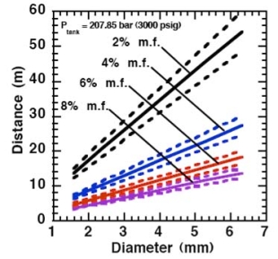 Fig. 5: Distances to concentrations of 2.0%, 4.0%, 6.0%, and 8.0% mole fraction on the centreline of a jet release from a 207.85 bars tank for various leak diameter obtained using the Sandia/Birch approach. The dashed lines indicate upper and lower bounds with ±10% uncertainty in the value of the constant K. (from (HoufW:2007)) ReferencesLIST,NS |