
|
BRHS /
Mitigation Measures
When handling hydrogen there are usually a number of unwanted potentially hazardous events that can take place with a certain frequency. The total sum of all consequences weighted by their frequency is normally referred to as the risk. This chapter will discuss various ways and methods that can potentially reduce the risk from unwanted events (i.e. a reduction of frequency and/or consequences). Consequences can include loss of life or injuries to people, property as well as reputation and more. The measurement unit for risk can be e.g. money, as all consequences may have a estimated price. Quite often, though, a risk assessment will focus on potential for loss of life. There are a number of possible unwanted events when handling hydrogen. Depending on setting and surroundings, the hazard will vary strongly. While a significant leak of hydrogen gas may be harmless in an unconfined process plant scenario because all gas is rapidly disappearing due to its buoyant nature, a much smaller leak may lead to a disaster if ignited inside a building. Examples of hazardous events are e.g. Pressurized pipeline or vessel: Major rupture may this give strong shockwaves as well as significant loads due to dynamic pressure from the flow out of the pipeline. If ignited, fire may produce heat loads and radiation. Significant leak rates may lead to severe explosion scenarios with pressure effects in case of delayed ignition. Liquid hydrogen storage: If released the low temperature of the hydrogen can cause damage to surroundings. If container is exposed to a fire, a too rapid heating relative to overpressure venting can lead to a BLEVE with significant overpressures and fireball with heat and radiation loads if ignited. Releases in water can result in rapid phase transition (RPT) explosions with associated overpressures. Liquid releases of hydrogen can also lead to significant release rates, and may in some circumstances show dense gas behavior, which may lead to major fires or explosions with associated pressures and heat loads. Smaller releases may build up gas and lead to strong explosions inside confinements, in addition to smaller releases from hydrogen storage, transportation or equipment, utilities, these releases could come from batteries, nuclear radiation in water, electric arcs in oil, waste treatment (metal containing ash into water). One major concern is usually the pressure effects, secondary effects such as projectiles and building collapse are generally more of a concern than the direct pressure effects on people. Consequences like explosion wind, fire heat loads as well as asphyxiation may also be important for the risk. This section will aim at discussing and describing possible ways and methods to reduce the risk from unwanted events. It can sometimes be useful to separate between passive and active measures. A passive measure is already in place and activated when the unwanted incident takes place, whereas the active measure requires some kind of detection and activation before it is applied. Due to the nature of hydrogen, with the wide flammability and high reactivity, the use of active measures can be a challenge. In risk assessments one will normally also include a certain probability that the active system fails to activate. Measures discussed can either be applied to mitigate, control or prevent the event (fire triangle approach removing oxygen, ignition or hydrogen), or to protect people or equipment from the consequences of a given event. Some examples of protection measures are indicated. Dispersion process, limiting amount of flammables:
Fire, limiting fire loads and consequences:
Explosion, limiting pressure generation and consequences:
Since the list of possible scenarios is very long, this selection will not cover all possible ways of reducing risk. One very important thing to notice is that some of the measures may seem contradictory from a risk point of view, and it is not obvious whether risk is reduced or increased. Examples are removal of ignition source vs. ignition on purpose. If gas clouds are always ignited small, the frequency of explosion may be increased, but the consequences likely reduced, giving a hopefully acceptable risk. Another example is increased confinement, which can reduce cloud size, but will often increase pressure and probability of unwanted consequences. Most of the previous work on protection measures has been focusing on less reactive hydrocarbon gases or even dusts. Because the properties of hydrogen are very different (order of magnitude lower Minimum Ignition Energy, much wider flammability, much higher burning velocity, more likely to detonate, more difficult to inert and more), it is not obvious that these measures will do any good mitigating hydrogen. Important aspects are:
A further general problem with mitigation systems is that they are generally tested for idealized situations (empty spherical vessel with central ignition), but then applied in real life situations for which geometry will influence performance. It may therefore be necessary to focus more on preventive measures, apply safety methods that exploit the buoyancy effects, and also put more weight on creative passive ways to reduce risk. The latter can be e.g. “soft barrier” methods [Tam, 2000] to reduce the size of dangerous flammable clouds, avoid flames to burn into congested areas, and also fill parts of the volume with inert balloons that will reduce combustible volume, but be compressed when overpressure builds up. A further discussion on such measures will be found in a later section.
Explosion venting of equipment and buildingsIntroductionVenting of deflagrations is recognized as a most widespread and cost-effective explosion mitigation strategy. The methods are based on the two following observations/assumptions:
The leading “Venting of Deflagration” guidelines from the USA, NFPA-68 [NFPA-68, 2002], has history back to a temporary explosion venting standard from 1945. NFPA-68 has been updated with input from various sources, much of this is done in Europe with very significant contributions from Germany [Bartknecht 1993]. Based on numerous experiments and analytical considerations vent nomograms were developed for numerous dusts as well as some gases, including hydrogen. When developing vent guidelines and nomograms, a number of assumptions, simplification and limitations will have to be defined. Since the flammables shall be categorized by reactivity, it is important to avoid situations where the flames get too turbulent, e.g. due to flame accelerating objects inside the room, or because the length/diameter ratio is too large. For this reason such guidelines will normally require that there are no obstructions inside the room and a maximum aspect ratio to be valid. This way, a significant part of the real life scenarios to be protected will fall outside the limitations of such guidelines. Other situations which may be difficult to cover with simple analytical equations or nomograms include the use of vent ducts, connected vessels, layout (geometry/vent distribution), non-ideal conditions (elevated or reduced temperature, pressure and oxygen concentration) and more. In a recent effort to improve the venting guidelines and reduce the number of situations where these can not be applied, a new European Vent standard prEN14994 [prEN14994 2004], has been developed. This has been available in a draft version since 2004. In NFPA-68 relations exist for hydrogen, but only for strong enclosures and with no turbulence generating obstructions. Similarly the prEN14994 can calculate relations for hydrogen, but only for situations “essentially free for turbulence generating obstructions”, with aspect ratio L/D < 3 and only allowing vessel strength of up to 2 bar. The possibility to use these standards and guidelines for the dimensioning of practical hydrogen applications may therefore be limited. The strict limitations when handling hydrogen are based on experimental observations, the presence of small objects or deviations from required shape of vessel may increase the severity of explosions dramatically. Experiments [Pförtner, 1985] have shown how the flame exiting from a vented vessel may experience a deflagration to detonation transition outside the vent, and [Dorofeev, 1995] showed that a detonation may be initiated inside the vent. In at least one of the experiments in the FLAME facility [Sherman, 1989] DDT and detonation flames inside the geometry may have been caused by lateral venting. For most situations with flammable gas either outside or inside a building/vessel, this may not be too much of a concern. More detailed information about the various standards and guidelines can be found by reading them. Standards and guidelines will usually be based on a coarse description of a room/vessel and the important parameters. Detailed layout, vent position, geometry and likely ignition location may be poorly described. One should therefore expect that the guidelines in most cases will give a conservative estimate of the expected overpressure, if applicable at all. Computational Fluid Dynamics (CFD) has a better possibility to describe the actual situation, including the situations not covered by the guidelines. One should in general expect to be able to reduce conservatism when applying more advanced methods. From CFD it is also possible to obtain more details about pressure loads, like duration, shape and distribution, and further how the venting will influence blast pressures and drag loads outside the vent openings. As the quality and applicability of CFD-tools vary significantly, one should make sure that the CFD-tool is properly validated against a wide array of relevant experiments, and also that validation based user guidelines exist and are followed by the user. 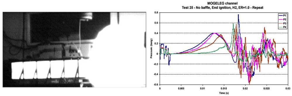 Figure 1-99 Example of a vented hydrogen explosion from GexCon small scale channel with L/D about 4. In the NFPA-68 (2002) guidelines, vessels with 2 < L/D < 5 will require a higher vent area than for L/D < 2, and the guideline will predict a maximum explosion overpressure of 1.05 barg for the given experiment. Previous versions of NFPA-68 (e.g. 1988 edition) use one relation for L/D < 5, and would predict only 0.50 barg. As can be seen from the experimental pressure traces to the right, an overpressure of around 0.8 barg is seen in the experiment.
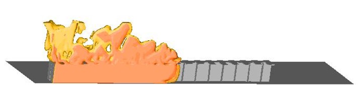 Figure 1-99 Computational Fluid Dynamics can be useful when estimating required venting. Distributed venting, like the transverse venting shown above [Hansen, 2005], can be very efficient to keep pressures low. CFD-tools can take into account detailed layout, including shape of vessel, position and shape of vent openings, presence of geometry and more. In addition to maximum pressure, shape and duration of pressure as well as distribution in space can be found using CFD.
Example of venting guideline: NFPA-68The current edition of NFPA 68 (2002) includes the vent sizing correlation, which reflect results presented by Bartknecht [1993]. The test data used in support of the correlation covered a range of volumes from 1 to 60 m3 and four gases: methane, propane, city gas and hydrogen. Additional testing was also carried out to study the effect of increasing values of vent relief pressure, Pstat. The result of all this work is summarized by the following formula: $$ A_v \; = \;\left\{ {\left( {0.127\;Log_{10} K_G \; - \;0.0567} \right)\;P_{red}^{ - \,0.582} \; + \;0.1754\;P_{red}^{ - \,0.572} \;\left( {P_{stat} \, - \,0.1} \right)} \right\}\;V^{2/3} $$  The range of applicability of the above equation is given by:
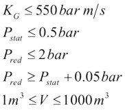 For elongated vessels (2 < L/D < 5) a correction to the vent area is indicated in the NFPA standard, which is calculated in accordance with the following formula:  More details will be found in NFPA-68 (2002) Example of venting guideline: vent sizing of enclosures with hydrogen-air mixtures (V. Molkov)Explosion venting is the most wide spread and cost effective deflagration mitigation technique. Design of explosion vents may be based on the vent sizing correlations or application of the computational fluid dynamics. In general, the vent sizing formulas of NFPA 68 standard [1] and its European version EN 14994 [2] are not applicable to hydrogen because of its high K_{\mathrm G} index. Indeed, the vent sizing area formulas adopted by NFPA and EN standards are only applicable for a value of K_{\mathrm G} inferior or equal to 550 bar-m/sec. As shown in Figure C.1 of Annex C of the NFPA 68, the K_{\mathrm G} index of hydrogen increases with volume. For instance, the K_{\mathrm G} index of hydrogen rises from 550 bar-m/sec for a volume of 0.005 m3 to 780 bar-m/sec for a volume of 10 m3. This simply means that the NFPA 68 vent sizing approach for hydrogen-air mixtures is not applicable for volume larger than 5 L. Examples of comparison between the experimental data and the predictions by the innovative vent sizing technology [3] and NFPA 68 [1] are presented in Table 1. The predictions of the NFPA 68 were calculated using the value K_{\mathrm G}=550 bar-m/sec. Experimental configurations included sphere, cylinder and tunnel. Hydrogen concentrations were in the range 10-30% by volume. The vent sizing of tunnels was as follows: the volume of hydrogen-air mixture represents the enclosure volume and the enclosure vent area is naturally equal to double the cross sectional area of the tunnel. Table 1. Comparison between experimental data and predictions by the vent sizing technology [3] and NFPA 68 [1].
a C - Central ignition; F - floor ignition. From Table 1, it can be seen that the vent sizing technology predicts reasonably well both vent area and reduced pressure for different conditions whereas the predictions of NFPA 68 are shown to be significantly overestimating or even underestimating experiments. The procedure for calculating the vent area in an empty enclosure or enclosure with insignificant influence of obstacles is as follows: 1) Calculate the value of the dimensionless reduced explosion overpressure \pi_{\mathrm{red}}=p_{\mathrm{red}}-p_{\mathrm{i}}.
2) Determine the value of dimensionless static activation pressure \pi_{\mathrm{V}}=\left(p_{\mathrm{stat}}+p_{\mathrm{i}}\right)/p_{\mathrm{i}}.
3) Calculate the value of the dimensionless pressure complex \pi_{\mathrm{red}}\pi_{\mathrm{V}}^{2.5} based on the data from the two previous steps;
4) Calculate the value of the turbulent Bradley number \mathrm{Br}_t by the use of one of the following two equations depending on the value of the above mentioned dimensionless pressure complex \pi_{\mathrm{red}}\pi_{\mathrm{V}}^{2.5}: \mathrm{if} \pi_{\mathrm{red}}\pi_{\mathrm{V}}^{2.5} < 1 \qquad \pi_{\mathrm{red}}\pi_{\mathrm{V}}^{2.5} = 5.65 \mathrm{Br}_t^{-2.5}
\mathrm{if} \pi_{\mathrm{red}}\pi_{\mathrm{V}}^{2.5} > 1 \qquad \pi_{\mathrm{red}}\pi_{\mathrm{V}}^{2.5} = 7.9-5.8\mathrm{Br}_t^{0.5}
5) Using Figure 1, determine the appropriate values of laminar burning velocity and the expansion ratio for the suitable hydrogen-air mixture. For instance, for stoichiometric hydrogen-air mixture at NPT, the following values can be used for the purpose of vent sizing: E_{\mathrm{i}}=6.88, {S_u}_{\mathrm{0}}=1.96 m/s [7, 8]. The influence of the initial temperature on the laminar burning velocity can be extrapolated from the formula [9]
{S_u}_{\mathrm{i}}={S_u}_{\mathrm{0}} = \left(\frac{\displaystyle T}{\displaystyle 298}\right)^{1.7} where {S_u}_{\mathrm{0}} is the laminar burning velocity at NTP (see Figure 1); and T is the initial temperature.
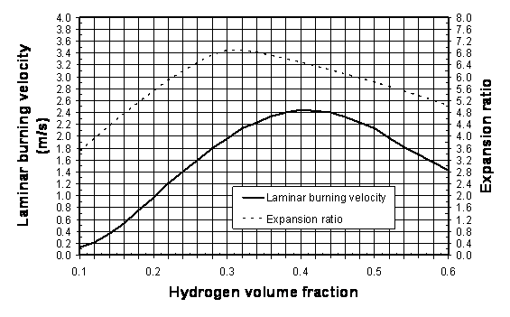 Figure 1: Laminar burning velocity and expansion ratio of hydrogen-air mixtures at NPT. 6) Determine the vent area by solving numerically the following transcendental equation (by changing area A until the right hand side of the equation is equal to the left hand side):
\frac{ \displaystyle \mathrm{Br}_t \sqrt[3]{36\pi_\mathrm{0}} V^{2/3}}{\displaystyle {c_\mathrm{u}}_{\mathrm{i}}\sqrt{E_{\mathrm{i}/\gamma_\mathrm{u}}}} = \frac{A\displaystyle \left(1+\pi_{\mathrm{\displaystyle}}\right)^{0.4} \left[1 + 0.5\left(\frac{A}{V^{2/3}} \frac{{c_\mathrm{u}}_{\mathrm{i}}}{{S_u}_{\mathrm{i}}(E_{\mathrm{i}} - 1)}\right)^{0.8}\right]^{0.4}}{\displaystyle \alpha \left(1 + 2 V^{0.94}\right)^{0.4}{S_u}_{\mathrm{i}}\left(E_\mathrm{i}-1\right)} where
The correlations have been calibrated up to date against experimental data for hydrogen-air deflagrations for the following range of conditions: L/D \le 4.2;
V \le 37.4 m3;
0.005 \le A/V^{2/3} \le 0.34;
0 \ \text{kPa} \le p_{\mathrm{stat}} \le 13.5 \ \text{kPa};
p_{\mathrm{i}} = \text{1 bar abs.};
0.22 \le \pi_{\mathrm{red}} \le 5.
Reference & sources
Venting of equipment (vent ducting)In the design of a venting system it is necessary to consider the hazards that can arise from the flame and hot combustion products that would be discharged from the vent. They should be discharged into a safe area, which is away from where any personnel may be present and so it does not cause any damage to surrounding equipment. This can be particularly a problem for vented equipment located inside a building. One way of overcoming the problem is by attaching ducting to the vent so the discharge can be directed to a safe area, preferably outside the building. The downside on the use of vent ducting is that it reduces the efficiency of the venting. The ducting will increase the flow resistance and there is the possibility of a secondary explosion of any unburnt gas initially discharged into the duct. The net effect is to reduce the flow through the vent and this lead to an increase in the reduced explosion pressure. To minimise the reduction in vent efficiency the ducting should be kept as short as possible, with no bends or large radius bends and have a cross-sectional area at least as great as the vent itself. Meeting the above guidelines is not always practicable and even when they are met it may still be necessary to increase the size of the vent to compensate for the reduced venting efficiency. Guidance on estimating the required increase in vent size is limited. The proposed European standard on the gas explosion venting and NFPA 68, on which the European standard is based, give formula for estimating the increase in the reduced explosion pressure for ducts with lengths of less than 3 m and for ducts with lengths between 3 m and 6 m. For longer duct lengths it will be necessary to determine the effect of the duct by appropriate testing of the actual duct configuration. In the NFPA-68 2002 version, there seems to be an error in the duct length formula as the duct length to be entered in the formula is not an absolute length but the ratio of length to duct diameter. This will be corrected in NFPA-68 2006 edition.
Active inerting, suppression and isolation systemsA number of active mitigation methods are applied in the industry to limit the consequences of accidental fires and explosions. In the following some of these methods will be described, with particular focus on their potential benefit with regard to protection against hydrogen fire and explosion scenarios. Systems using water will be discussed separately in the next section. The concept of constant inerting is also discussed, even if this cannot be considered to be an active method. The approach is however closely related to methods like rapid pre-ignition inerting or suppression. The method is also discussed elsewhere in this report, and only a brief description will be given here. Constant inert gas dilution to prevent ignition and combustionThe typical approach is to dilute the atmosphere with sufficient amount of inert gas to prevent ignition and combustion. In situations where human activity is not required, one may also replace all the air by inert gas. The inert gas will typically be N2, CO2, or special mixtures to allow human breathing but no combustion (of hydrocarbon gas at room temperature) like InergenTM (mainly Ar and N2, some CO2), ArgoniteTM (Ar, N2) or similar. The approach is typically applied for situations where the risk from accidental explosions or fire would be unacceptably high, examples are:
Challenges with such systems are that they would require proper control systems to maintain the intended dilution level. Good routines and safety systems may be required to limit the hazard to personnel, either from volumes 100% filled with inert gas, but also possible malfunction of people-safe inert gas dilution systems. Since flammability limits are much wider and dilution levels to obtain inert atmosphere are much higher for hydrogen compared to natural gas, gas dilution to levels where humans can breath but flames not propagate is more challenging when handling hydrogen. In Table 1-4 a comparison of inert levels between natural gas and hydrogen is shown for some relevant inert gases. None of the inert gases most frequently applied for hydrocarbon gas allowing presence of people will be safe for hydrogen. Halons would be more efficient, however, the Montreal protocol with the ban on halons due to the ozone depletion effect removes this option. HFC-gases like e.g. HFC-236fa can be an option. But due to greenhouse gas effects (high Global Warming Potential) these agents are banned for fire protection use in some countries, and subject to prohibitive environmental tax in others. Since HFC-236fa has shown better performance than HFC-227ea, and will be safe for people at higher concentrations, this gas could give a certain protection against hydrogen ignition and flame propagation. The solution is questionable, as ignition should still be expected for H2 concentrations in the range 10-20%. If inerting fails, the HFC-gases may in certain circumstances decompose or take part in combustion, enhancing pressure build-up and the gases developed during combustion are toxic. It should be noticed that the values shown in Table 1-4 are for normal pressure and temperatures, and that higher inerting levels will be required e.g. for elevated temperatures [see www.safekinex.org]. Butane (C4H10) has also been added to Table 1-4 as another creative approach would be to add sufficient amount of other flammables so that the total mixture becomes too fuel rich to burn. It is expected that 8.5% butane (UFL) mixed in the air could prevent any mixture with hydrogen at ambient temperature and pressure to become flammable. Courage is however required to apply this approach as the mixture will become flammable again once diluted with air. One should then consider the possible benefits achieved from reduced reactivity due to butane dilution of hydrogen versus the increased amount of flammable substance due to the added butane. As a conclusion, good solutions for the protection of rooms with presence of people have not been identified. For rooms or situations with no presence of people, full inerting, for instance with nitrogen, can be applied. For industrial process flows containing pure hydrogen, purging with inert gas could also be performed prior to shut-down or start-up to avoid explosions. 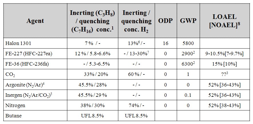 Table 1 4: Efficiency, environmental impact and hazard for people for different inert gases, most of the data is extracted from [Isaksson, 1997] and for conditions near 25şC 1atm.
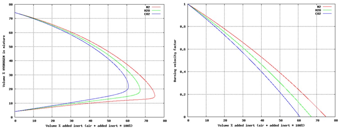 Fig 1 14: These plots show necessary inerting level (left) for hydrogen-air with added inert gases N2, H2O or CO2, as well as the assumed impact on laminar burning velocity (right). Relations shown are those used in the CFD-tool FLACS, and are based on [Zabetakis, 1965]. Pre-ignition inert gas dilutionWhen the probability for accidental leaks is low, or there is a need for presence of people, it may not be practical to keep an inert or partially inert atmosphere constantly. Another alternative then will be to activate inert gas dilution on leak detection prior to ignition. Depending on scenario, the optimal choice of system will vary.
There will be some challenges when applying pre-ignition inert gas dilution. One will be to detect the problem and activate the system before dangerous pockets of flammable gas have built up. Personnel safety is another issue. The system must not be activated before people are safe. Further, the distribution of inert gas must be as even as possible or give better protection where the flammables are found. If CO2 is injected in a dense gas layer near the floor and the leaked hydrogen creates a flammable cloud near the ceiling, the protection is limited. On the other hand, one should also be aware that the turbulence created when injecting inert gas can make an explosion more severe if it gets ignited. A further issue to consider is a safe handling of the overpressure from injection systems with outflow of potentially explosive mixtures. Explosion suppression and fast acting valvesIn the powder handling industry dust explosions can be a severe hazard. In many situations explosion suppression is used to quench flames, either inside a vessel or in the pipe connection between vessels to prevent escalation into further vessels. An alternative to suppression (chemical isolation) in the pipes between vessels will be explosion isolation by fast acting valves closing the pipe mechanically. More information on suppression can be found in [Moore, 1996]. To apply similar methods for hydrogen flames may be possible, but will be much more challenging. While turbulence from a suppression system alone may be sufficient to quench dust flames, the same turbulence will likely accelerate hydrogen flames. To apply suppression at hydrogen flame detection inside a room or vessel will likely make things worse, as the turbulence will strongly enhance the flame spread and no quenching can be expected. Further challenges are the short time window to detect and evenly distribute agent, the influence of real geometries that may prevent an even mixing of inert, and also the evaporation time for e.g. HFC-gases (these are normally stored as a liquid). In work towards protection of transformers, room suppression against hydrogen flames was tested [Hansen, 2002] with limited success. The chemical or mechanical isolation of hydrogen flames burning from one vessel towards the next should be a more realistic task. Challenges will still be to detect and activate the suppression system or isolating closing valve fast enough. With fast deflagration or detonation mode flame propagation, the flame may propagate 10-20 m in 10 ms. Success with such a concept therefore depends on early detection (before flame is entering the pipe to be isolated) and rapid activation of measure. For chemical isolation (suppression) one must ensure that enough inert gas is injected for a sufficiently long period. One must be prepared that the flame may have a delayed entrance to the pipe after detection, so that the suppression system must release enough suppressant to inert a sonic flow through the pipe at least until the flame has reached the barrier. Other issues to consider is to what extent a hydrogen detonation wave will manage to propagate through a chemical barrier in its early phases, and further to what extent a plug of hot reaction products after the chemical barrier can re-ignite gases in the second vessel. Mechanical isolation seems safer if this can be done fast enough. Challenge here will be to dimension the system to withstand a reflected detonation wave. Computation ToolsNo calculation tool has the necessary functionality and models to precisely evaluate all the aspects discussed. The physics is complex, but a range of CFD-tools can still be useful. The GexCon FLACS tool can be used to evaluate the transient distribution of inert gas, either from a suppression or inerting system. Further the influence of inert gas dilution on explosions and the effect of fast acting valves can be predicted. Water based protection systemsWater is extensively used for fire and explosion protection. It has a high heat capacity (per mass) and heat of evaporation, water is easily available, safe and friendly to the environment, and can be applied both as liquid particles (efficient distribution) and vapor. Examples of applications are
Fine aerosol droplets [< 10 micron]: These are difficult to generate and distribute mechanically in large quantities. This can either be done when large droplets (0.5-1 mm) break up in the explosion wind ahead of deflagration flames. Another alternative for confined situations will be by flashing of superheated water. For explosion protection the water mist must be of this size class to have a beneficial effect on the flame. Larger droplets will not manage to evaporate in the reaction zone of the flame. Due to their size, these small aerosol droplets will follow the flow. If significant flow velocities are present in the accident scenario, they may be transported away by wind or convection flow from fire and have no beneficial effect. Explosion tests with such a fine aerosol system from Micromist Ltd. [Hansen 2002b, 2002c] have shown that stoichiometric propane can be made inert, while a significant pressure reduction 50-70% was achieved with hydrogen using 4 litre/m3 prior to ignition in a 50m3 vessel with low congestion and relative low vent area. Compared to natural gas, tests seemed to indicate that of the order 3 times more water mist must be applied for hydrogen to achieve similar relative pressure reduction. Fine mist [30-200 micron]: These can be generated by commercial mist/fog nozzles. Due to a better ability to penetrate the flow, but limited size giving fast evaporation, they may be useful for fire mitigation. For explosion protection this droplet size will have a limited or even negative effect, as the turbulence from their distribution will accelerate flames, but the evaporation time scales are too large for deflagration flames. GexCon has performed hydrocarbon explosion tests using fog nozzles for mitigation. This resulted in increase of pressure instead of a decrease. The reasons for this were strong initial turbulence from sprays and combined with limited mitigation due to too large droplet size for efficient evaporation (but too small droplets to achieve droplet break-up). Droplets from sprinklers [400-1000 micron]: These can be generated from normal sprinklers at 3-7 bar water pressure. These droplets may have a positive effect on large-scale fires, but may be less efficient for smaller fires compared to the previous category. For unconfined and partially confined explosions, these droplets may be very efficient. Due to their size they are not so much influenced by strong natural ventilation or buoyant convection flow from a fire. When explosion starts, the sprays will initially accelerate flames. Very soon these droplets are broken up into very fine mist particles due to the forces from the expansion flow ahead of the flame. The fine mist will be efficient against explosions as the flame reaction zone is diluted with fine aerosol particles. The efficiency of such a system increases with scale, with amount of water, with equipment congestion and with decreased confinement. For natural gas hazards on offshore installations, typical application rates are 10-25 litre/sqm/min depending on area to be protected. For explosion protection, 10 litre/sqm/min is not necessarily sufficient if the confinement is significant. For hydrogen the beneficial effect may be even harder to achieve, this will be discussed in the next section. Advantica [Catlin, 1993, Selby, 1998, Al-Hassan, 1998], and GexCon [van Wingerden, 1997, 1998 and 2000] have performed numerous tests with sprinkler systems to study explosion mitigation for natural gas. This has shown a very beneficial effect at large-scale when confinement is low. With low congestion and high confinement, less good results are seen, and in some situations the use of water deluge may make the explosion consequences significantly more severe.. Despite a significant research effort on water mitigation of natural gas, limited work has been done on hydrogen. The effect of inert water vapor on hydrogen flames is one exception. In the following it will be discussed to what extent water can be used to improve hydrogen safety. Water based systems and effect on hydrogen safety
For a situation where accidental releases of hydrogen can take place, a sprinkler system with water could enhance mixing and avoid stratification effects. If the total amount of hydrogen that can leak is small compared to room volume, this can be a good idea as very reactive flammable clouds may be avoided. For larger releases, this may strongly increase the hazard, as a large homogeneous cloud at dangerous concentration may form. A forced ventilation or fan system could have the same effect. If there is a wish to add heat to released gas to enhance buoyancy of the cold plume, water curtains directly downwind or around a cryogenic hydrogen spill dike could be to some help. It should be confirmed that no ignition hazard is introduced due to static electricity. Static electricity from nozzle systems does not seem to be a problem for natural gas clouds exposed to deluge, however, minimum ignition energy for hydrogen is 10 times lower than for propane. Against fire it is assumed that water can be applied to cool equipment exposed to radiation or flame impact, to cool the flames, and possibly also to set up a radiation shield where needed. Quite a lot of water vapor will normally be needed for extinction of hydrogen flames. Turbulent jet flames may lift-off with increased water vapor level. To quench hydrogen flames may be very difficult, and will seldom be a beneficial result in relatively confined situations as an uncontrolled leak and potential explosion may follow. For explosion mitigation an aerosol water system based on flashing of substantial amounts of superheated water (4 litre/m3 water at 180şC/10 bar) has been shown to reduce hydrogen explosion pressures significantly. More than a factor of two reduction of overpressure was achieved at 15-20% H2 concentrations [Hansen, 2002b]. More water is expected to improve the effect further, but the release of hot water may lead to a significant temperature increase and a certain overpressure at activation. Best effect will be seen if injected short time before ignition. The suppression of the hydrogen flames inside a room with such a system will likely not work, due to problems with activation time and turbulence from release. In special situations a system could still work, for instance being released in compartments where the flames have not reached yet. Steam (water vapor) would be expected to have a similar (or better) effect, but the distribution of significant amounts of steam will take time and build up pressure. Water sprinkler systems activated at release prior to ignition could be expected to have a mitigation effect on hydrogen explosions in certain situations. Significant more water than applied for natural gas would be needed. Potential problems include the possibility that turbulence from sprays may quickly accelerate the flames into DDT and detonation, and then the water sprinkler will not be expected to have a mitigating effect any more. The much lower minimum ignition energy for hydrogen compared to natural gas may also increase the likelihood for ignition from static electricity in connection to the water sprinkler systems. The conclusion will be that potential benefits from using water-based protection systems within hydrogen safety may exist. For protection against fire effects, traditional methods should be applicable. There are few good solutions at the moment to handle explosions, more work will be needed to identify and validate good systems. Further development and testing of the fine aerosol technology from superheated water should be performed and the potential benefits and problems for sprinkler systems should be investigated. Tools and methods:No calculation tool has the necessary functionality and models to precisely evaluate all the aspects discussed. Several CFD-tools can be used to study the effect of deluge on dispersion. Some CFD-tools have models for the effect of deluge on deflagration flames, these are mainly valid for natural gas. The GexCon FLACS tool has modified guidelines for hydrogen and deluge, but experimental validation is limited.
Passive systemsIn this section various passive methods and their potential influence on the hydrogen safety will be discussed. Passive measures will include elements such as “Inherently safe design”, “Soft barriers” as well as certain protection measures that are constantly in place and thus require no maintenance. Because of the high reactivity of hydrogen, and the limited benefits expected from active measures, special consideration should be given to find the optimal passive protection methods. For gas explosions, some best practice advice can be found in [Bjerketvedt, 1997], see examples in Figure XX. 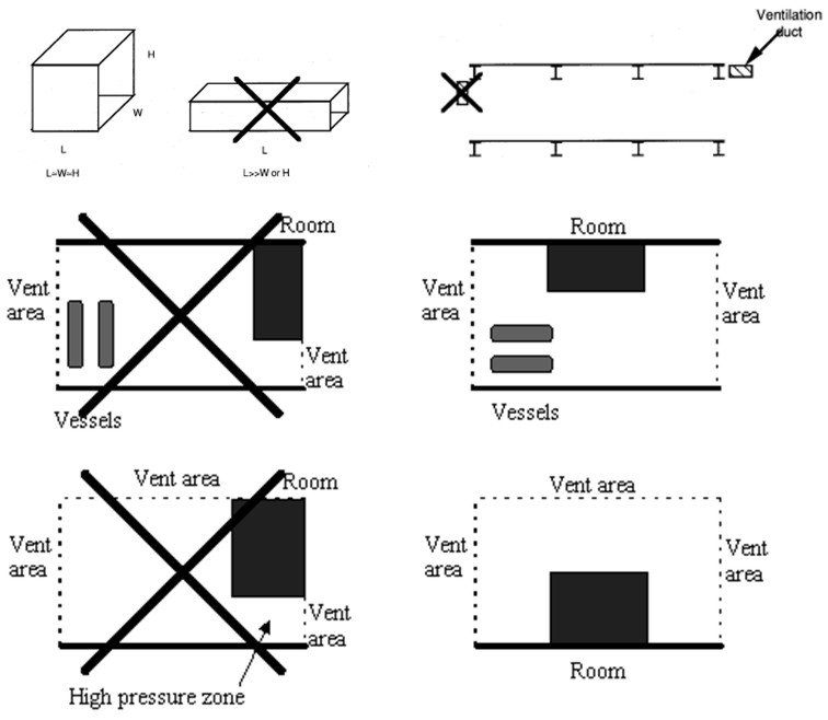 Figure XX: Some illustrations from Gas Explosion Handbook [Bjerketvedt, 1997] indicating best practice layouts for explosion exposed areas. Inherently safe designThe main focus here should be to avoid significant flammable gas clouds. Some focus will also be on limiting overpressures if an explosion takes place. Both these goals can be achieved by minimizing the confinement (the optimal wall is no wall). The strong positive buoyancy of hydrogen should be exploited, and one should ensure that released hydrogen finds its way upwards without meeting too much confinement. In outdoor situations, this can be ensured by proper design of ceilings and covers. Large high-momentum leaks inside a process area may still generate significant cloud sizes. If this turns out to be a problem, methods can be applied to reduce the momentum of horizontal leaks, e.g. putting up vertical walls around the likely leak locations. By reducing the momentum of the leak, it will much sooner find its way upwards. This may reduce cloud sizes (but increase likelihood of small explosions as more frequent smaller leaks may now generate flammable clouds). Such a measure should therefore not be applied without a proper risk evaluation. Another issue in the design is that different units should be separated so that the gas cloud from one unit does not reach the next unit. In semi-confined situations, one should further ensure that natural ventilation in combination with buoyancy effects will be as efficient as possible preventing gas cloud build-up for different wind conditions. Again focus should be on designing the ceilings so that buoyant layers of gas will find its way out of the vent openings. For a more confined situation it will depend on the leak rate whether a low momentum release (more stratification, beneficial for large amounts released or if gas near ceiling is quickly removed) or high momentum release (more mixing, beneficial provided concentration can be held e.g. below 8%) is preferable. A casing around the leak exposed equipment can ensure a low momentum leak. Similar effects may be achieved by applying weak barriers, like curtains. This may let some of the gas through, but may reduce the size of very flammable gas clouds. If a gas cloud is generated and ignites, presence of large vent areas will usually be an advantage to limit explosion pressures. If the vent areas are well distributed, this may reduce the flame acceleration through the geometry and the severity of the explosion. A strong feedback from external explosion into the chamber increasing the turbulence and flame speeds may also be less likely when vents are distributed. In some situations it will be an advantage that the vent panels close after an explosion to limit access to oxygen for the following fire. The congestion level should also be made as low as possible, to limit turbulent flame speeds. In areas exposed to hydrogen leaks, the area near the ceiling should be given particular attention, as the gas is likely to collect there. It may then be a good idea to limit the equipment density near the ceiling, to avoid equipment that will accelerate flames in that region. If there are significant support beams below ceiling, these may both be an advantage as they may influence the shape of the gas cloud, but also a disadvantage accelerating flames. When designing such facilities, one should have a philosophy about this before deciding on the detailed layout. It is not always straight-forward to choose the optimal design based on the guidelines above. Several of the considerations will depend on the frequency and consequences of various incident scenarios. If one design choice is taken, one should expect this to increase the frequency/consequence of certain incidents, and reduce the frequency/consequences for other. When evaluating these issues it is important to apply methods that take the complexity of the phenomena into consideration. If consequence tools are to be applied, this will in many situations mean that CFD-tools should be applied, as simplified guidelines will not pick up the physics. Protection wallsOne approach to protect sensitive equipment from explosion effects will be to design some kind of barrier between a source of explosion and a sensitive target. This is sometimes done in connection to the handling of explosives, and also for situations in the chemical industry to protect surroundings from high pressure tanks with potential unstable chemicals that may explode [Herrmann, 2005]. It is also sometimes used to deflect flames in connection to explosion venting, either to prevent people from being killed by fast vented flames, or to protect buildings directly outside an explosion vent. Like for many other mitigation measures the design and optimization of a protection wall is not straight forward. Important design questions are: Where to locate the wall? The wall can either be located close to the source to absorb the energy from the explosion or venting, or it can be located close to the target to shield the target from pressure waves. For a deflagration it is in general difficult to identify the exact position of the explosion source, and it will usually not be practical or cost-efficient to use this as a mitigation measure. One exception is when there is a vent opening, in this case one may know where the energy comes from, and it will be possible to design a protection wall. The alternative approach will be to design a protection wall in front of the target. In order to have a good effect, one will have to study the detailed interaction between blast waves and the wall & building complex and optimize size & position based on such a study. It can be a challenging task to design a good protecting wall, and in most cases it will be better to spend the same resources strengthening the target building. How large should the wall be? This can be a difficult question to answer as it will depend on several parameters, including position and volume of source explosion relative to object to be protected. For a geographically well defined detonation or vessel burst situation that can be considered as a point source, an optimization of wall design may be possible, for a less well defined source a significant conservatism will normally have to be included. How strong must the wall be? If the wall is located near the source, it has to be stronger than if it is located close to the target. In both cases, it should not generate projectiles as a result of the blast loads. If the incident is statistically rare, it may be acceptable that the wall is damaged by the incident. By studying such approaches with protection walls against blast waves, one will normally realize that the effect of shielding walls is usually limited. Parameter studies may also show that it is fully possible to make the blast loads worse depending on location and size of the shielding wall. This can be partly because the pressure will go around the wall on all sides (above and to the sides), and these pressure waves will be deflected and may again meet behind the wall. In the planes where these deflected waves will meet, one may experience higher pressure loads than for the reference case with no walls. Another issue is that the pressure waves coming from a different angle compared to the case with no protection wall may be more dangerous giving a stronger reflected pressure. 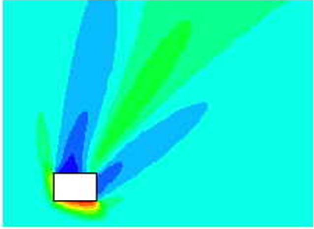 Figure X.X Due to reflection effects, the pressure in front of a “protection object” may be significantly higher than the free-field blast pressure. But even behind an obstacle, interference may lead to overpressures higher than without the object present. The plot shows enhancement factor for simulated pressure waves relative to free field blast, in this case the object may enhance observed pressure behind the object by more than 30% locally (the effect will depend on the strength of the shockwaves).
In the following an example of the testing and modeling of protection walls will be given. Forecast of blast wave propagation and impact force which is applied to the protective wall In case if explosion accident occurs, it is necessary to have some measures in order to minimize the disaster of material and personnel on the surrounding area. For this purpose, the design conditions of protective wall was investigated in order to obtain more efficient reduction of blast wave by means of calculating the blast wave propagation using compressible fluid simulation for the postulated explosion accident. The benefit of protective wall installation was examined based upon the numerical simulations of blast wave propagation by the BAAL which is open source code of Los Alamos National Laboratory. Fig. 1 shows a reduction effect of explosion overpressure by various protective walls. 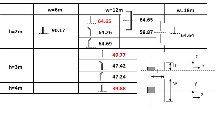 Fig.1 Comparison of reduction effect of explosion overpressure of various protective walls The value in Fig. 1 represents a reduction effect of explosion overpressure, and this is calculated as per cent value of explosion of overpressure to that without protective wall at a distance of 10 meter downstream from the protective wall. Based upon the result which is shown in Fig. 1, it becomes clear from this simulation that protective wall should have certain width at least 12 meter, and the reduction effect of explosion overpressure greatly depends on the height of protective wall and does not depend on its configuration. Experimental evaluation and numerical simulation of the damage of surrounding structures by an explosion accidentExplosion experiments were carried out in order to evaluate the damage of surrounding reinforced concrete (RC) structures and to enable a structural design of it by numerical simulations. (See Fig.2) 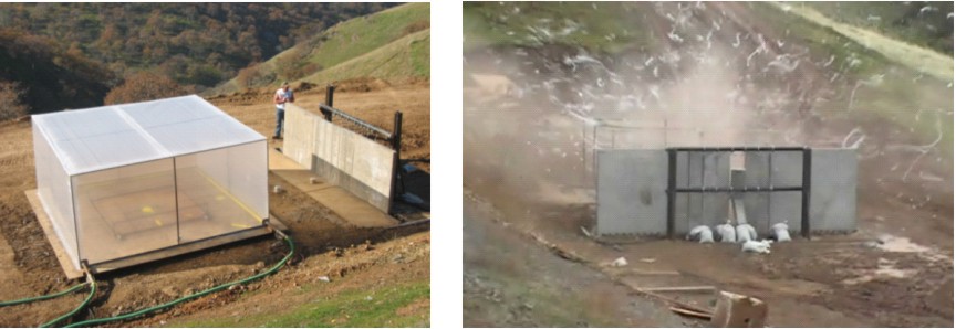 Fig.2: Experiment of hydrogen explosion and RC structure damage (left:Experimental system, right:A moment of explosion)
For the experiment, pre-mixed 37 m3 of 30% hydrogen with air was detonated with the RC test pieces located at 5 meter from explosion center, and response and damage of test pieces were observed. The number of RC test pieces is 22 with a different height, thickness, bar arrangement and steel ratio. Table 1 shows the result of experiments with a broad range of conditions from elastic stage to breaking. Table 1: Experimental results on RC structure damages caused by hydrogen explosions 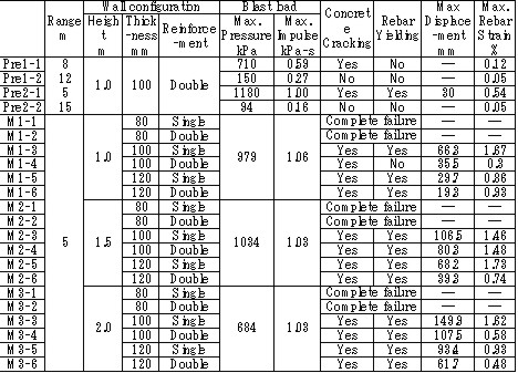 The explosion results show that response of the structures has a significant time lag behind the blast wave propagation. And because a trace of crack shows an evidence of higher order deformation mode, the damage of RC structure is caused by a vibrational phenomenon which is dependent on the natural frequency of it. (See Fig.3) 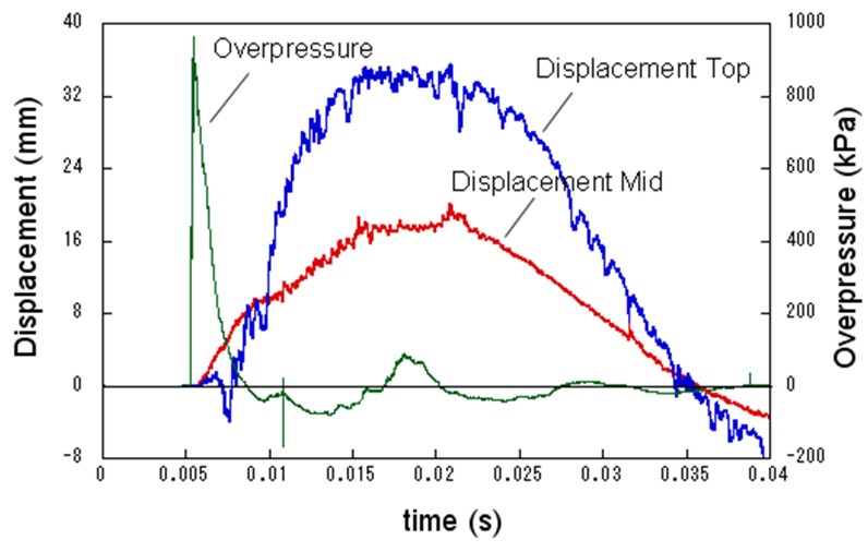 Fig.3 Typical displacement response Result obtained from the coupling of a blast wave analysis by AUTODYN and a response analysis by FINAL which is analysis software for a structure developed by Obayashi Corporation agrees well with the experimental result. (See Fig.4) Therefore, this phenomenon is found to be simulated with above-mentioned software. 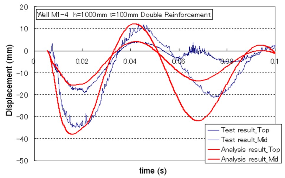 Fig.4 Comparison of simulation and experiment concerning displacement response Soft barriersThe concept of soft barriers for explosion mitigation was discussed in [Tam, 2000]. A soft barrier could be a polyethylene sheet preventing gas to enter into regions where explosions could become more severe due to pressure piling or reflections. Another soft barrier could be to put a cover around a congested pipe bundle. A gas explosion will accelerate much less going past one large “cylinder” compared to a pipe bundle. A third example would be to fill the upper half of a room with balloons. A released gas will only be able to fill half of the volume. If this explodes, the overpressure will manage to expand as the balloons get compressed. If the balloons also fill space between beams (repeated beams would normally accelerate the flames), the effect from such measures can be very significant. The possibilities with such soft barriers are numerous. Another example could be a pattern of regular vertical curtains. Workers could easily walk through the curtains, so the limitations to the normal work operations could be limited. A high momentum jet release on the other hand would soon lose its momentum and move upwards due to buoyancy. The curtains would also limit the mixing of gas. The flammable cloud size would then be limited (a small rich region, other lean regions, and some regions with no gas at all). Once the explosion would start, the soft barriers will act as weak vent panels in all directions. 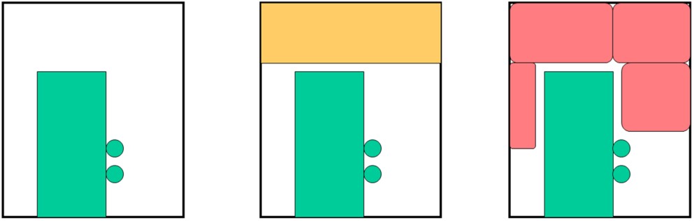 Fig.x.x Two creative ways to reduce worst-case explosion consequences are illustrated. In central picture the volume exposed to flammable gas is reduced by introducing a false weak ceiling, in right picture balloons reduce volume that can be occupied by flammable gas, these will be compressed in case of pressure buildup and thus reduce the explosion consequences.
Flame arrestersFlame quenching and quenching diameter Cold walls quench the flame over a fairly long distance. The observation led Sir Humphrey Davy to the invention of the miners safety lamp in 1815 and has been used ever since in the construction of various explosion proof equipment including flame arrestors used to protect storage, distribution and chemical processing facilities containing flammable gases from fire and explosions. Typically the arrestors are composed of metal plates with orifices, wire mesh screens, porous sintered metal elements, etc. The flame quenching by walls can be due to cooling and chemical effects in particular destruction of radical chain carriers. By testing different mixtures of the same composition diluted in different proportions by argon and helium which changes the ratio of diffusion coefficients and thermal conductivities of the mixtures without affecting the chemistry it was proven that heat transfer is by far the dominating mechanism. Then simple physical considerations lead to the conclusion that the quenching distance dq should be proportional to the flame thickness that in turn is related to the laminar burning velocity, SL 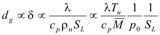 (1) (1)where, λ is the thermal conductivity, cP is the specific heat at constant pressure, ρ is the density, T is the temperature and In some methods the flame is quenched using a circular tube in which case, one often speaks of the quenching diameter D0. In other methods it is convenient to quench the flame by a tube of slot like cross section, in which case one speaks of the quenching distance referring to the width of the slot. 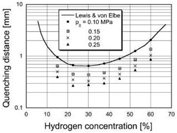 Fig 1: Quenching distance as function of hydrogen concentration at various initial pressures.
In Fig .1 quenching distances are plotted as function of hydrogen concentration in air at 300 K for various initial pressures after Yang et al. [Yang, 2003]. In the figure also data of Lewis and Elbe [Lewis, 1987] are shown for comparison. The quenching distance has its minimum at about 30% vol. of hydrogen i.e. practically at stoichiometry. Other geometries provide different quenching distances. The geometrical factor could be calculated from the requirement that the heat loss rate at which flame is quenched is a constant independent of tube geometry. The geometrical quenching factors were studied by Berlad and Potter [Berlad, 1955]. The following relations were proposed for D0, quenching distance D1 and quenching by a rectangular slit D2 with the shorter side Dr and longer side b.  (2) (2)Other geometries were also analysed. Although the predicted and observed values agreed well, systematic deviations were observed, which required empirical correction factors (typically of the order of 10%). The length of the quenching hole is unimportant, both orifices in foils and thick plated provide the same results. Several investigators looked for an effect on quenching distance of the nature of the wall and found none, even when the walls were coated with special chain breaking salts of various efficiencies. Maximum experimental safe gap (MESG) Forced flow conditions, like the ones occurring during explosion, make a difference. Thus, the following problem is of importance. A mixture is ignited, or explodes in a closed vessel. The same mixture surrounds the vessel. What is the maximum safe width of a slit in the vessel (sometimes referred to as the “maximum experimental safety gap” MESG) for the flame to spread outside. Propagation of the flame under such condition is a much more complex process due to the domination of non-stationary and gas-dynamic phenomena. A landmark analysis of the problem was provided by Phillips [Phillips, 1963]. Discussion of the problem is beyond the scope of this note and as an indication of the orders of magnitude in Table 1 we give the width of the “explosions proof” slits and D1 for several mixtures after Chomiak [Chomiak, 1990]. It is interesting to note that MESG is by a factor of two larger than quenching distance at explosion pressures for most fuels, except acetylene where it is less than half. This aspect of flame quenching is poorly understood and requires more work. These values relate to stationary flame. If the gas flow is in the direction of flame propagation, a smaller gap is needed to quench the flame, and conversely. If the gas velocity is high enough, a condition can occur in which a flame propagating against the flow is stabilized at a constriction and causes local overheating.  Table 1: Comparison of MESG and quenching distances for several mixtures [Chomiak, 1990] Deflagration Flame Arresters A flame arrester, or flame trap, is a device used to prevent the passage of a flame along a pipe or duct. A flame arrester is generally an assembly of narrow passages through which gas or vapour can flow, but which are too small to allow the passage of flame. Flame arresters are generally distinguished as end-of-line or in-line arresters. There are three types of arresters:
The operation of type 1 arresters is generally treated in terms of the mechanism of quenching and heat loss. Desirable properties of a flame arrester are high free cross-sectional area available for flow, low resistance to flow and freedom from blockage; a high capacity to absorb the heat of the flame, and the ability to withstand mechanical shock, including explosion. The design of flame arrester depends on the combustion properties of the flammable mixture and on the function and location of the arrester. The size of the aperture through the arrester is determined by the quenching distance of the flammable mixture. The diameter of the aperture of an arrester should be smaller than the quenching diameter by at least 50%. The performance of an arrester is affected by the temperature. The quenching distance increases as the temperature increases. It is approx. inversely proportional to the square root of the absolute temperature. Hydraulic, or liquid seal, arresters contain a liquid, usually water, which serves to break up the gas stream into bubbles and so prevents passage of the flame. Velocity flame stoppers are arresters used in end-of-line applications. Their function is to prevent a flame passing from downstream to the upstream side. The principle of their operation is to assure that the velocity of the upstream gas passing through the arrester is sufficiently high to prevent a flame propagating through the arrester from the downstream side. The velocity necessary to prevent flashback through apertures larger than those which would give quenching is given by the equation [Hajek and Ludwig, 1960]: uT = 0.2015gLD where: D – internal pipe diameter (m) gL – laminar velocity gradient (s-1); it is a function of the gas and its concentration; for hydrogen its maximum value is equal to 10 000 s-1
uT – turbulent flashback velocity (m/s)
More details on flame arresters, including technology and list of manufacturers can be found in the book by Grossel [Grossel, 2002]. Several types of flame arresters have been tested for hydrogen service and found acceptable for quenching of hydrogen-air and hydrogen-methane-air mixtures. Howard et al. [Howard, 1975] conducted experiments on three types of flame arresters for quenching fuel mixtures of hydrogen and methane with air. Tests were run at pressures of 0.02 and 0.08 MPa and feed gas temperatures of ambient, 423 K, 473 K and 523 K. In these experiments only the velocity stopper was able to stop all flame propagation. Some crimped metal ribbon flame arresters have been tested for hydrogen service and can be used. [Protego, 1993) has both deflagration and detonation flame arresters, ranging in size from 10 mm to 400 mm, approved in Germany for mixtures of hydrogen and air in all ranges of concentration. Enardo [Enardo, 2005] has also in-line flame arresters for hydrogen-air mixtures. NAO has designed and successfully tested and provided a hydraulic flame arrester for hydrogen-air applications. Rao [Rao, 1980] also provides information on a hydraulic flame arrester that was designed and used successfully for hydrogen service in a nuclear power plant. Codes and standardsFlame arresters are the subject of a number of codes and standards in different countries. In the UK BS 7244 – 1990 [BS, 1990] covers the testing of arresters. In the USA the Underwriters Laboratories standard UL 525-1989 [UL, 1990] deals with construction and testing. Also in the USA the American Petroleum Institute has API PB 2028.2002 standard [API, 2002]. Germany has legally backed standards on the same aspects. The International Maritime Organization (IMO) also has requirements for flame arresters [IMO, 1984]. A new CEN European standard, EN 12874 was issued in 2001 [CEN, 2001]. This is very comprehensive standard covering many aspects of flame arrester technology. Detonation arrestersNone of the deflagration arrester designs can withstand a detonation. Therefore the detonation flame arrestor was designed. Detonation arresters are devices designed to withstand and extinguish the high speed and high pressure flame front that characterizes a detonation propagating through a piping system. Therefore, a detona¬tion arrester must be able to withstand the mechanical effects of a detona-tion shock wave while quenching the flame. Some designs have a "shock absorber" in front of the flame arresting element to reduce both the high pressure shock wave and the dynamic energy and to split the flame front before it reaches the flame arrester element. Another design variation has what is called a "detonation momentum attenuator" (DMA) [Westech 1989]. Detonations occurring in piping have velocities of about 2000 m/s, or greater, and in closed process vessels and equipment can generate pressures from 20 to 100+ times the initial pressure. Detonation flame arresters are available for hydrogen as both unidirectional or bidirectional types. When installed in a vent manifold system the flame arresters on the tanks may be unidirectional or bidirectional, depending on the manufacturer's recommendations. They should preferably be installed in a vertical orientation, so that if liquid is present, the arrester will drain. If they must be installed in a horizontal orientation, they should be provided with drain connections. Most detonation arresters have crimped metal ribbon arrester elements, although expanded metal cartridges are also used. Arrester elements for detonation arresters are usually longer than for deflagration arresters. Detonation flame arresters impose higher pressure drops than deflagration flame arresters due to heat transfer requirements, they are heavier because of structural requirements, and they are typically more expensive. Instantaneous impulse pressures caused by the shock waves of overdriven detonation subject the arrestor to forces up to 34,000 kPa(g) at atmospheric initial pressure. Volume filling of tanks with thin metal objects with large surface The fact that surfaces will cool a flame can also be exploited in a different way. If a potentially flammable volume, like a fuel tank in a fighter plane or a racing car, is packed with small elements built up from thin metal foils, this will represent a very large surface area. The volume occupied by the metal object may still only be of the order a few percent, so the influence on the tank performance may be limited. A flame burning in this volume will then experience a very substantial heat loss, and may quench. Such methods have been applied for certain applications for hydrocarbon vapors of moderate reactivity. Since the quench distance and MESG is one order of magnitude smaller for hydrogen than for typical hydrocarbons, requirements for fineness of metal structures will be much higher since 10 times shorter distance between cells will require 1000 times more cells in 3 dimensions. It should still be possible to benefit from such a method, even if the design would allow the flames to burn, heat will be extracted from the burnt gases which could both reduce the burning velocity and terminal pressure. If the cells of the metal structure are too large, they could accelerate the flames. One example of a company manufacturing such a concept is [eXess, 2006].
Emergency responseEmergency response methods available for a hydrogen “loss of containment” incident will to some extent be similar to emergency response to loss of containment for other gaseous fuels. Active fire fighting is not as effective as for petrol or diesel, and more emphasis will thus have to be laid on extensive emergency response planning. The emergency response plan should reflect the foreseen major hazards and aim at minimize the risk to people. Emergency response planGeneral principles for emergency response planning may, in the absence of guidelines specific for hydrogen, be extracted from other areas where extensive emergency planning is seen as essential. Guidelines for emergency response for offshore installations are given in [ISO, 2000]. A basic principle is that emergency planning should be based on systematic identification of hazards, followed by evaluation and risk management. The initial step in emergency response planning would be the emergency response strategy, describing the general philosophy on how the organization, procedures, equipment training and other measures are supposed to work together to deal with foreseeable incidents – even in the case of failure of an emergency response measure. For a hydrogen leak the direct mitigation means could for instance be deactivation of ignition sources upon gas detection, to prevent ignition. (Ignition source control is described in Ch 5.6.6.) This measure may not be effective, possibly even leading to ignition, and warning and escape procedures as well as egress routes will thus have to be part of the strategy. Moreover, as these measures both rely on the detection and communication of a hydrogen leak, detection (See Ch 5.7.1) and communication should have a high reliability. Communication is a key element in any emergency response plan. Effective communication will involve technical measures, organization, procedures and training adapted to each other and to the overall strategy. If communication fails, effective emergency response is not possible. Technical communication measures could initiate automatic actions such as shut down of electrical power supply, or initiate an alarm, emergency ventilation, enabling manual (human) intervention or escape. Technical communication measures will also be needed for mobilization and communication within the emergency response organization and for mobilization of external resources. All of these measures will have to have a high reliability, and in cases where human action is intended (mobilization, intervention or escape), the recipient’s ability to receive the message and discern the essential information must also be considered. Effective emergency response will also require an organization intended and prepared for emergency response. The lines of communication should be well known and worked in, preferably the same as for daily operation. Emergency procedures, and especially the function and use of communication equipment, should be known and tested within the organization. Escape/evacuation of people should be part of the initial planning of any new or modified installation. Escape routes are easy to implement at the design stage, but may be rather expensive or nearly impossible to implement if thought of too late. The principle of two escape routes from all areas regularly occupied by humans is laid down in most countries building regulations and should also be applied for outdoor facilities such as refueling stations. Bearing in mind refueling stations may be placed in congested areas and close to a highly trafficked road, this may not be straight-forward to accomplish. Liquid spillLiquid spill on water Spill of liquid hydrogen on water may lead to Rapid Phase Transition (spontaneous and explosive boiling of liquid hydrogen) due to the rather favorable heat transfer conditions and a practically unlimited reservoir of heat. The phenomenon is described by several sources, e.g. by [Hightower, 2004] for liquid natural gas (LNG) on water, where the temperature difference is less than for liquid hydrogen and water. Emergency response in such a case should include warning of boats in the area against sailing into the gas cloud. In some cases even car traffic may have to be stopped or re-directed. Warning of other people in the area, especially downwind of the release is also important, though the gas cloud may not be of such duration to expect any benefit from evacuation of people. Liquid spill on ground Spill of liquid hydrogen on ground can be expected to give less rapid evaporation than spill on water. The spread of liquid may be constrained, either by design of storage facilities or by natural formations. The best industry practice for storage of flammable liquids or condensed gases would be to lead liquid spills away from storage tanks (as well as temporarily stored transport tanks) by sloping ground (ditch) a collection basin, minimizing the liquid surface and thus minimizing evaporation. Hydrogen pool fires are described in Ch. 3.1.8.6. Prevention of ignition would normally require a larger safety distance than the protection of people from a pool fire. Emergency response should encompass warning of people in the area and re-routing of traffic to prevent cars from driving into the gas cloud. Gaseous releaseGaseous releases and dispersion of released gases are described in Ch. 3.1.1 and 3.1.2. Guidelines for emergency response for gaseous releases can be found in offshore standards, e.g. from [ISO, 2000 and 1999]. Though hydrogen’s properties are different from those of petroleum gases, there are also similarities: Methane is buoyant in air, and methane releases are often seen as the most hazardous flammable gas releases on offshore installations because methane gas will not sink towards sea level. A number of general principles for danger limitation should be transferable to hydrogen releases:
Hydrogen fireHydrogen gas fires are described in Ch. 3.1.8.7. An ignited gas leakage is not easy to extinguish, and the principle normally applied is to protect the surroundings as far as possible from the effects of the fire and prevent escalation. Guidelines for fire control and fire load protection can be found in [ISO, 1999]. The general principles are summarized below:
Safety distancesA safety distance is the required distance between the location of a gas leakage and the object to be protected which takes account of the evolving flammable atmosphere as well as of the heat and pressure wave resulting from a possible ignition. This separation distance is usually determined as a function of the quantity of hydrogen involved. It may be fixed on the basis of credible events and can be defined according to physically defined criteria, e.g., the dose of thermal radiation or the peak overpressure, to have reached a certain threshold value. Distance requirements may be reduced by the use of barricades. A minimum safety distance is desirable for economic purposes. The safety distance guidelines approach described in the following is simplified. Such simplified approaches may not be applicable in situations where confinement and congestion may collect gas and influence the flame acceleration. For certain conditions LH2 releases may show dense gas behavior, and if such a dense cloud of cold hydrogen-air mixture will enter a partly confined and congested region, one should not expect simplified safety distance guidelines to be valid. Another aspect is the risk of projectiles. Even if the blast pressure hazard is acceptable at a certain safety distance, dangerous projectiles may be thrown much further away. One major disadvantage using simplified methods for safety distances is that the lack of detailed description of the actual facility will give very limited credit to safety measures. One can therefore expect that the estimated safety distance is either significantly higher than necessary, or the guidelines are generally non-conservative. Today, more refined methods exist that can take into account a larger number of parameters, in particular safety measures, and for most situations it should no longer be considered responsible to apply simplistic safety distance guidelines developed 30-50 years ago (in the pre-computer age). In a study from 1960 [Zabetakis 1960] investigating the vaporization of LH2 and the ignition of H2-air vapour clouds above LH2 pools, a conclusion was made that the quantity-distance relation which was valid at that time is very conservative. The new recommendation as shown in Fig. 5-x1 as a step function is based on the assumption that the total content of an LH2 storage tank of up to 45 t or 640 m3 is released and ignited. The solid curves represent the estimated distances at which thermal radiation values reach a value of about 84 kJ/m2, a limit that is expected to produce flesh burns and ignite certain combustible materials. Curves are given for different humidity concentrations in the air where the severest case would be a zero water vapor content meaning that an essential radiation heat sink will be absent.  Fig 0 1: Industrial storage standards for H2, LNG, and gasoline in the USA, from [Zabetakis, 1960] A basic prerequisite is the knowledge of the source term which is dependent on leak size and thermal dynamic conditions of the leaking substance. A problem is given by non-quantifiable leakages, e.g., from cracks in welding seams. Quantity-distance relationships are usually different for people and for less demanding equipment, e.g., adjacent storage tanks, working buildings, or distinguished with respect to fireballs, shrapnel, structural response, or physiological effects (heat radiation). They also may differ for experimental and storage areas. A comparison of industrial storage standards for hydrogen, LNG, and gasoline is given in Fig. 5-x2 [Hord, 1978].  Fig 0 2: Industrial storage standards for H2, LNG, and gasoline in the USA, from [Hord, 1978] The following two figures show the quantity-distance relationships for LH2 storage containers assuming no barricades. Fig. 5-x3 applies to the protection of personnel and inhabited buildings from hydrogen fire and from shrapnel in explosions. The respective separation distance between storage containers is given in Fig. 5-x4.  Fig 0 3: Quantity-distance relationship for protection of personnel and inhabited buildings near liquid hydrogen storage containers in the USA, from [Hord 1978]  Fig 0 4: Quantity-distance relationship for protection of adjacent liquid hydrogen storage containers in the USA, from [Hord 1978] Design and operation of H2 and LH2 storage installations is regulated under the US OSHA (Occupational Safety and Health Administration) regulations as part of 29 CFR (Code of Federal Regulations). Here the minimum safety distance to be provided between the installation and people or property is defined as 15.3 m (50 ft) for gaseous H2 amounts > 425 Nm3. For LH2 tanks containing more than 2.27 m3 (600 gallons), the respective distance must be at least 23 m [US-DOT, 1997]. For hydrogen stored at US refueling stations, existing ASME pressure vessel standards apply requiring various distances between the pressurized tanks and public facilities depending on the amount of fuel stored. Current safety distance restrictions are significant. If reduced separation distances are desired, respective safety implications need to be investigated [Bevilaqua, 2001]. On-board hydrogen storage tanks are being covered by US-DOT regulations. They appear to be reasonable in their present form [Bevilaqua, 2001]. In Japan, respective safety distances rules have to meet the “High Pressure Gas Safety Law” (see also Fig. 5-x6). It prescribes at present the H2 pressure at filling stations to be not higher than 40 MPa. The respective upper limit for vehicle tanks is 35 MPa. There are activities ongoing to shorten the presently valid safety distances for H2 refueling stations. The corresponding investigation includes H2 gas leakage experiments plus respective simulation calculations for demonstration purposes and also tests with ignition of the escaping gas as well as the effect of barriers. Safety zones around storage tanks for liquefied gases according to the German law are described in Fig. 5-x5 for both above-ground and underground tank arrangement [Westfalen, 2001].  Fig 0 5: Safety zone arrangement for above-ground (top) and underground (bottom) storage tanks for liquefied gas with RI = 1 m and RII = 3 m, from [Westfalen, 2001]
Fig. 5-x6 gives a comparison of minimum safety distances between LH2 storage systems and inhabited buildings as a function of LH2 mass as were fixed in codes and standards from different institutions and countries, respectively. The curves illustrate the variation in conservatism of these institutions that generate safety criteria.  Fig 0 6: Safety distances (please note scale change on the ordinate), from [Verfondern 1999] Curves 1 and 3 from [Edeskuty 1979], 2 and 6 from [Japan Society for Safety Engineering], 4 from [Zabetakis 1961], 5 from [Doehrn 1984]. A formula for the safety distance is generally acknowledged to have the form R = k * M1/3 (5-1) where R is the safety distance in m and M the mass of the flammable substance in kg. The relation may be modified by damping parameters, if some sort of protective measure is applied, e.g., wall or earth coverage. The k-factor depends on the building to be protected (from German recommendations: 2.5 - 8 for working building, 22 for residential building, 200 for no damage) and on the type of substance. The above mass-distance relation applying a k-factor of 8 in combination with an overpressure history to be sustained has been used in the German legislation on the protection of nuclear power plants against external explosions [BMI, 1976]. It applies to explosive substances which are handled in the neighborhood like production sites, waterways or trans-shipment places, railways, roads. Explosive substances which are required for the plant operation, are not included. In this guideline, a distinction is also made between different kinds of flammable masses. The distance between the NPP and locations where explosive substances are handled shall be calculated according to the following mass - distance relation R = 8*L1/3 (5-2) Furthermore the safety distance has to obey a minimum of 100 m. If M is the maximum possible explosive inventory of a production facility or a storage tank or the biggest pipeline section between isolating equipment or transportation container in kg, then L is defined as the TNT equivalent in kg for explosive substances;
In terms of hydrogen, this is equivalent to a reduction of the k-factor from 8 m/kg1/3 down to 6.3 for gaseous H2 and to 3.7 m/kg1/3 for liquid H2, respectively. In the USA, it is judged according to the US-AEC Regulatory Guide 1.91 that structures, systems, and components important to safety and designed for high wind loads are also capable of withstanding pressure peaks of at least 7 kPa resulting from explosions. No additional measures need to be taken, if the equation R = 13*W1/3 (5-3) is met, where R is the safety distance [m] from an exploding charge and W is the mass of TNT (equivalent) [kg] of the exploding material (see solid line in Fig. 5-x7). For the LNG storage tank of the HTTR/SR system, the 400 m3 of LNG correspond to a mass of 169 tons of LNG, and this to a TNT equivalent of 1859 tons which then translate into a safety distance of as long as 2.2 km. This approach appears to be unrealistic for the HTTR/SR system considering the fact that much larger stationary LNG tanks up to 200,000 m3 ( R 18 km) have been established worldwide. Aspects not taken into account here are the different explosive characters of a liquefied gas and a TNT explosive, the possibility of additional options offered by the 1.91 guideline, and finally the extreme unlikeliness of the total tank content to “explode” rather than assuming less conservative “design spills”. 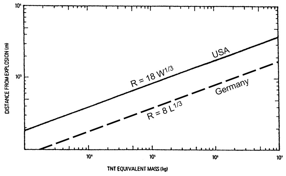 Fig 0 7: Safety distance as a function of the quantity of released liquefied gas according to the BMI guideline and the US regulatory guide 1.91, from [Verfondern, 2004] Knowledge gapsWith regard to mitigation of hydrogen explosions, the main knowledge gap may be the lack of identified useful methods for mitigation. Whereas numerous methods can be applied for hydrocarbon gas explosion mitigation, few of these will have a sufficient beneficial effect on hydrogen flames. Due to the lack of good ways to mitigate hydrogen explosions, efforts to avoid significant flammable clouds to build up in partially confined and congested areas should have a main focus. Some areas where increased understanding could help to estimate the risk better, is for instance to get a better understanding of spontaneous ignition phenomena. If larger high-pressure hydrogen leaks would always ignite within fractions of a second, like seen in some jet release experiments by [Groethe, 2006], this would be important for the estimated risk and risk reduction measures for such situations. The implication would be that for such releases, there is no point to work actively to minimize ignition sources, there is too little time for any action to be taken, and fortunately, there is no risk for a very large gas cloud to be generated. More work will be needed to understand these phenomena better. It is unclear under what conditions, such as volume size, aspect ratios, and obstructions, etc., the mitigation by explosion venting would be applicable for hydrogen. Available vent-sizing methods and guidelines have very limited applicability for hydrogen. More experimental data and analysis is necessary. Available guidelines on safety distances related to siting of hydrogen facilities are controversial and do not provide clear input. Water deluge is potentially a mitigation measure that could reduce the flame speeds and explosion severity. This measure works very well for natural gas explosions, provided the degree of confinement of the gas cloud is limited. Potentially, there will also be situations where water deluge may mitigate hydrogen flames, this should be investigated experimentally at realistic scales. One possibly very critical situation will be a massive release of liquid hydrogen on a warm day with low humidity. In such a situation the evaporated gas cloud may form a neutral or dense hydrogen-air cloud, which may represent a very significant hazard, in particular if it will become filled with obstacles or become partly confined. Typical obstacles could be a forest, a process plant, industrial or domestic houses etc. One possibility to mitigate this hazard will be to introduce sufficient heat to the cold evaporated hydrogen-air mixture for it to become more buoyant. This can for instance be done by water spray systems with small droplets to maximize the heat transfer. For the increased understanding of this hazard, it would be useful to see large-scale experiments which both demonstrates the possibility to generate a dense gas hydrogen-air mixture on a warm day with low humidity, and then repeat the experiment applying water sprays to add heat to the plume. Another critical situation is the transport of significant amounts of hydrogen through tunnels. If significant leaks may take place, or if the gas is on purpose released in an emergency situation, the confinement of the tunnel may make this a severe risk scenario. For situations with significant releases of hydrogen inside a tunnel, no good mitigation methods have been identified so far. The best method for mitigation of risk is to build up a good understanding of physics and to be able to model the various risk reduction methods available. With a CFD-tool available that can model the consequences of a given incident, as well as the consequences of mitigated incidents, one will have the possibility to optimize the design and mitigation methods for the situations considered. When doing so, it is important not only to consider one particular incident, but to study the range of possible incidents, to estimate the overall effect of mitigation measures. Optimally, a probabilistic risk assessment could be carried out, in which the effect of mitigation is assessed. This could e.g. be along the lines recommended for Norwegian offshore installations [Norsok, 2001]. To follow this approach, a validated CFD-tool will be required, which can model as much as possible of the phenomena and mitigation methods of interest.
<< Detection Measures | Content | Safety of Hydrogen Technologies: Examples >> |
|||||||||||||||||||||||||||||||||||||||||||||||||||||||||||||||||||||||||||||||||||||||||||||||||||||||||||||||||||||||||||||||||||||||||||||||||||||||||||||||||||||||||||||||||||||||||||||||||||||||||||||||||||||||||||||||||||||||||||||||||||||||||||||||||||||||||||||||||||||||||||||||||||||||||||||||||||||
 is the average molecular weight, and the subscript u denotes the unburned state. The above equation is a surprisingly exact one, and only the additional, typically weak, pressure dependence of the SL introduces some discrepancies. It is interesting to note that only about 22% of the heat generated by the flame per unit surface must be removed in order to quench the flame.